Category
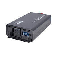
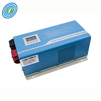
- Pure sine wave Inverter with LCD
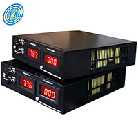
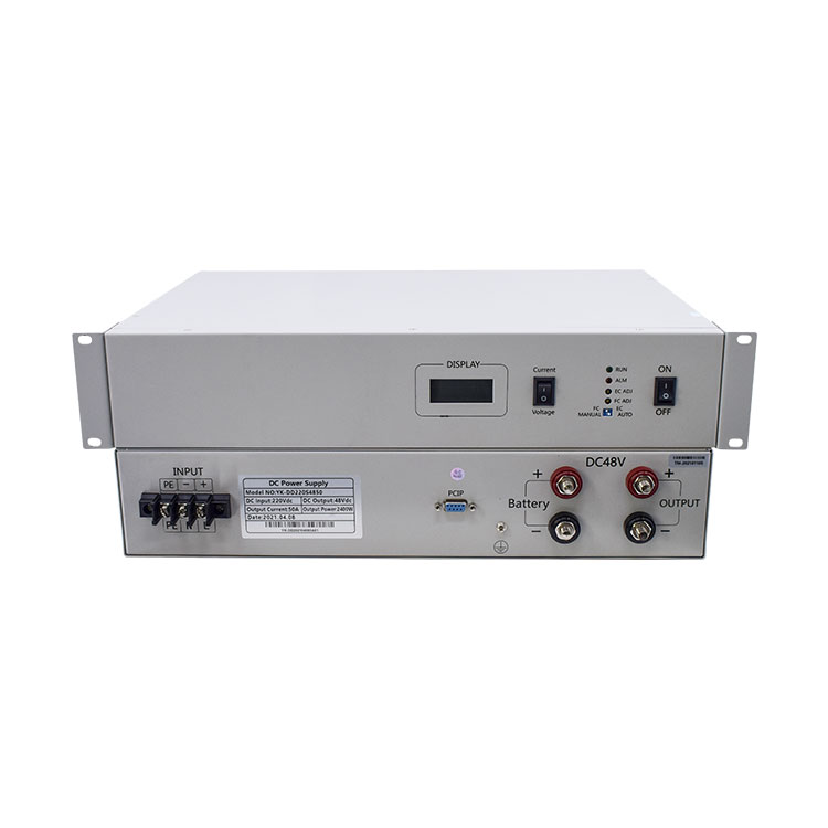
- Adjustable DC Power Supply
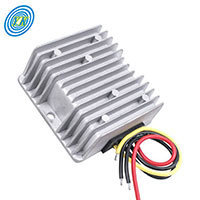
- Buck DC-DC Converter
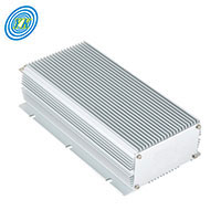
- Boost DC DC Converter
- Buck/Boost DC DC Converter
- New Isolated DC DC Converter
- AC to DC Converter
- Bared Board DC DC Converter
- Low frequency Inverter with Charger
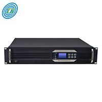
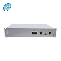
- Telecom Inverter
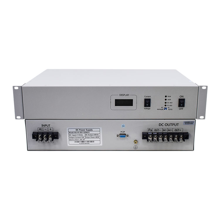
- 19 inch DC-DC Converter
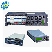
- Rectifier & Rectifier System
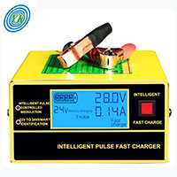
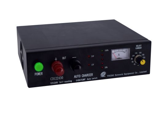
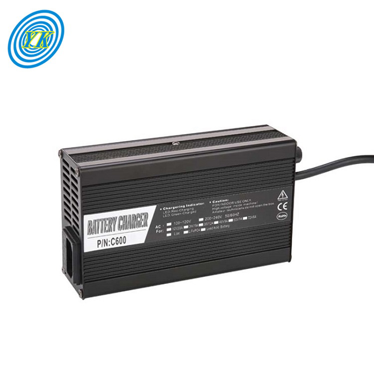
- Battery Charger - (Civil use)
- Battery Charger - (Industry)
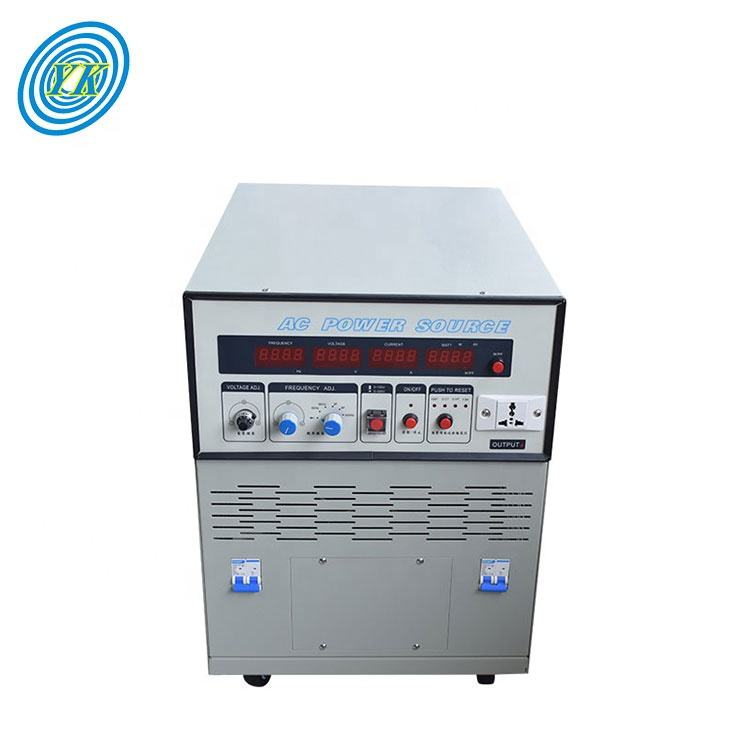
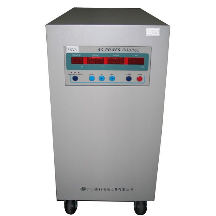
- Frequency Converter
- PDU-Power Distribution Unit

- Inverter built-in MPPT
- MPPT Controller
- Portable power station

- Transformer
- Switching Power Supply
- Plating rectifier
Battery Charger Market Dynamics: Growth, Innovation, and Future Trends
Click: 911 Date: 03/01/2024 3::14::33 PM
Battery Charger Market Dynamics: Growth, Innovation, and Future TrendsThe Battery Charger market is experiencing significant growth, driven by a combination of factors including the increasing adoption of electric vehicles (EVs), rising demand for portable electronic devices, and growing awareness of battery health and maintenance. The market was valued at USD 21,782.90 Million in 2022 and is projected to reach USD 35,096.74 Million by 2030, growing at a CAGR of 6.4% .Key growth drivers include:The rapid growth of the EV market, which is driving the demand for battery chargers, particularly fast chargers and home charging stations.The popularity of smartphones, laptops, tablets, and other portable devices, which is creating a steady demand for portable battery chargers.Consumers becoming increasingly aware of the importance of proper battery care, leading to a rise in demand for intelligent chargers that optimize battery life.Government regulations and incentives promoting EV adoption, which is indirectly driving the battery charger market 1.In addition to these, the growing demand for wireless charging technology, the advent of smart and connected chargers, and the expansion into emerging markets present significant opportunities for battery charger manufacturers. Wireless charging technology offers convenience and eliminates the need for cables, while smart chargers with features like monitoring, diagnostics, and remote control are gaining traction and offer new revenue opportunities.Regional insights indicate that Asia Pacific is the largest and fastest-growing market for battery chargers, driven by the increasing demand for EVs and portable electronics in China and India. North America is a mature market, but the adoption of EVs is expected to drive further growth. Europe has a strong focus on sustainability, which is driving the demand for smart and energy-efficient chargers.Innovations in the market include the introduction of new chargers capable of charging an EV in 15 minutes, such as ABB's 350kW EV charger, and the development of a 350kW charging network across Europe by Porsche and Ionity. Other notable developments include Anker's launch of a 100W GaN charger with multiple ports for various devices and Apple's release of its MagSafe Duo Charger with wireless charging for iPhones and Apple Watches.In summary, the Battery Charger market is poised for significant growth, driven by technological advancements, regulatory incentives, and the increasing demand for portable electronic devices and electric vehicles. This growth is expected to continue, with innovations in charging technology and the expansion into emerging markets playing a crucial role in the market's future trajectory.The Battery Charger market is characterized by a competitive landscape with several key players. These players are known for their innovative products and services across various sectors, including automotive, consumer electronics, and industrial applications. The market segmentation is primarily based on product type, application, and category, each with its unique market dynamics and trends.Major Players in the Battery Charger Market:Accutronics LimitedAnalytic Systems Ware Ltd.Anoma CorporationAssociated Equipment CorporationEnergizer Holdings Inc.Exide TechnologiesFerro Magnetics CorporationFRIWO AGHindlePower, Inc.Panasonic Corporation of North AmericaPhihong USA CorporationPowerbase Industrial (HK) Ltd.Saft S.A.Salcomp PlcSchumacher Electric CorporationScud (Fujian) Electronics Co. Ltd.Shun Shing Standard Corporation Development Ltd.Spectrum Brands Inc.Uniross Batteries S.A.SYuasa Battery Inc.These companies are at the forefront of the battery charger market, offering a wide range of products and services tailored to different market segments and applications.Market Segmentation:Product Type: The market is segmented based on the type of battery charger, with wired chargers being the dominant segment in 2022 due to their reliable and smooth connection capabilities.Application: The market is further segmented by the application of the battery chargers, which can include automotive, consumer electronics, and industrial applications. Each application segment has its specific requirements and technologies.Category: The category segmentation encompasses the different types of batteries that the chargers are designed for, such as lithium-ion, lead-acid, and nickel-cadmium batteries.The competitive landscape and market segmentation highlight the diversity and complexity of the battery charger market, with key players and segments driving the industry's growth and innovation.Innovations in Charging Technology: Advancements in Battery ChargingThe evolution of battery charging technology has seen remarkable progress, introducing innovations that enhance efficiency, convenience, and safety. Here are some of the key advancements:Ultra-Fast Wireless Charging: The introduction of ultra-fast wireless charging promises to revolutionize how devices are powered, offering speeds that could charge devices in a matter of minutes. This development aims to eliminate the time-consuming process of traditional charging, making it a thing of the past.Enhanced Wireless Charging Range: Future advancements in wireless charging technology are expected to significantly expand the charging range, reducing the need for devices to be in close proximity to the charging pad. This innovation opens up new possibilities for wireless charging integration in our daily lives, offering more flexibility and convenience.Intelligent Wireless Charging: The development of intelligent wireless charging systems is a promising future innovation. These systems would automatically adjust the charging rate based on the power requirements of the device, optimizing the charging process for efficient and safe charging. This technology not only enhances the charging experience but also prolongs the lifespan of device batteries.Wireless Charging on the Go: The future of wireless charging technology also includes innovations that enable charging capabilities for a wide range of devices on the go, such as cars and wearable devices. This development aims to eliminate the need for cables or power outlets, making it possible to charge devices anywhere.Multi-Device Charging: Innovations in fast wireless charging have made it possible to charge multiple devices simultaneously, further enhancing convenience. This development allows for a more efficient use of charging infrastructure, reducing the need for multiple charging cables.Bidirectional Chargers: The concept of bidirectional chargers, which allow electricity to travel both ways, is another significant advancement. This technology enables electric vehicles to not only receive electricity for charging but also to send electricity back through vehicle-to-grid (V2G) energy transfer. This could lead to a more balanced energy grid and even allow homeowners to generate income from excess solar power.These innovations collectively point towards a future where charging technology is not only more efficient and faster but also more integrated into our daily lives, offering greater convenience and environmental benefits.North AmericaNorth America leads the Battery Charger market with a robust infrastructure, including significant manufacturers and consumers. The region's growth is supported by government incentives, environmental awareness, and investments in charging networks. Technological advancements, such as wireless charging systems, are accelerating the market's growth .EuropeEurope is a key market for Battery Chargers, focusing on the rapid expansion of charging infrastructure. Stringent emissions regulations and government support accelerate market development. This region's growth is driven by initiatives to establish charging infrastructure and increasing awareness of environmental concerns .Asia PacificThe Asia Pacific region exhibits significant growth potential due to a surge in electric vehicle adoption, particularly in China. The market is driven by infrastructure development, technological innovation, and the establishment of ambitious goals for the development of electric vehicles. The region's growth is fueled by government laws, expanding government programs, and reasonable pricing of electric charging stations and electric vehicles.Middle East & AfricaThe Middle East is gradually embracing Battery Chargers, with increasing awareness of environmental concerns. Initiatives to establish charging infrastructure contribute to market growth. Africa is an emerging market for Battery Chargers, with growing interest in electric mobility. Investments in charging stations and renewable energy sources offer opportunities for market expansion.Regional Specifics ImpactThe regional specifics, including government policies, environmental concerns, technological advancements, and the adoption of electric vehicles, significantly impact the Battery Charger market. These factors influence market growth, infrastructure development, and the pace of technological innovation across different regions.ConclusionThe Battery Charger market's regional dynamics are shaped by a combination of factors including government incentives, environmental regulations, technological advancements, and the adoption of electric vehicles. North America and Europe have established markets with supportive infrastructures, while Asia Pacific and the Middle East & Africa show significant growth potential due to rapid adoption of electric vehicles and technological innovations. Understanding these regional specifics is crucial for businesses looking to navigate the Battery Charger market effectively.Emerging battery technologies and future trends in the Battery Charger industry are shifting towards more efficient, cost-effective, and environmentally friendly solutions. This shift is driven by the growing demand for electric vehicles (EVs), renewable energy storage, and the need for sustainable energy solutions. Here are key developments and future directions:Lithium-Ion Batteries: Despite being a decades-old technology, lithium-ion batteries continue to evolve. Improvements in lithium-ion battery chemistries, such as lithium iron phosphate (LFP) batteries, are enhancing energy density, charging speed, and safety. LFP batteries, for example, have shown significant improvements in performance, with Tesla already adopting them in some of their vehicles.Solid-State Batteries: The search for alternatives to lithium-ion batteries is leading to the development of solid-state batteries, which could offer higher energy densities, faster charging times, and improved safety. Companies like Quantumscape are working on lithium-metal batteries, while others are exploring sodium-ion batteries, which could provide cost advantages.Sodium-Ion Batteries: Sodium-ion batteries represent a significant departure from traditional lithium-ion chemistries. These batteries could offer cost benefits due to the use of cheaper materials and are being considered for applications such as stationary storage and micromobility devices .Iron-Based Batteries for Stationary Storage: The demand for electricity storage is growing, leading to the development of iron-based batteries for stationary storage. Companies like Form Energy and ESS are making strides in this area, focusing on water-based electrolytes and different chemistries for improved efficiency and cost-effectiveness .Innovations in Anode Materials: Research into alternative anode materials, such as silicon and tungsten-carbon nanotubes, is aimed at increasing energy density and speeding up charging times. These advancements could lead to batteries that are more efficient and durable, particularly for EVs and grid storage applications .Future Trends in Battery Technology:Increased Energy Density and Efficiency: The ongoing development of new battery chemistries and materials is expected to lead to batteries with higher energy densities, longer lifetimes, and improved efficiency. This will be crucial for meeting the growing demand for electric vehicles and renewable energy storage.Safety and Cost-Effectiveness: A significant focus in future battery technology will be on improving safety and reducing costs. This includes the development of safer electrolytes and exploring new materials that can offer similar performance at a lower cost.Rapid Charging and Modular Batteries: The development of technologies for rapid charging and modular batteries is anticipated to make electric vehicles more practical for everyday use. Modular batteries could allow for faster charging times and easier maintenance, enhancing the overall user experience.Sustainability and Environmental Impact: As the Battery Charger industry evolves, there will be a growing emphasis on sustainability and minimizing the environmental impact of battery production and disposal. This includes the search for alternative materials and the development of recycling processes for used batteries.These trends reflect a shift towards more sustainable, efficient, and user-friendly battery technologies, driven by the need to support the growing adoption of electric vehicles and renewable energy sources.
Click: 706 Date: 02/29/2024 10::38::40 AM
Exploring the Diverse Landscape of Battery Chargers for Civil Use: Types, Technical Features, Applications, Installation, and Energy Storage SolutionsThe variety of battery chargers available for civil use encompasses several distinct categories, each tailored to specific needs and applications. These include:Home Battery Chargers: Designed for use within residential settings, these chargers are optimized for charging devices such as laptops, smartphones, and tablets. They often come with multiple charging ports and are equipped with safety features to protect both the device and the home's electrical systemPortable Battery Chargers: These are compact and lightweight, making them ideal for travel and outdoor activities. Portable chargers are equipped with USB ports for charging a wide range of devices and often include features like USB-C or lightning connectors for quick charging capabilitiesSolar Battery Chargers: These chargers harness the power of the sun to charge devices. They are particularly useful for outdoor activities, camping, and in locations with limited access to electricity. Solar chargers can be standalone units or integrated into solar panels to provide a continuous power sourceWireless Battery Chargers: As the name suggests, these chargers do not require a physical connection between the device and the charger. They use radio waves to transfer energy, making them convenient for charging devices without the need for cables. Wireless chargers are suitable for devices with built-in wireless charging capabilitiesSpecialized Battery Technologies: Beyond the general categories, there are specific technologies like Lithium Ion, NiCd, and Lead Acid that underpin various types of battery chargers. Lithium Ion batteries are known for their high energy density and long lifespan, making them popular for devices that require a lot of power. NiCd batteries offer a high discharge rate and low self-discharge rate, suitable for applications requiring high power output. Lead Acid batteries, while older technology, remain reliable and affordable for many civil use applications, especially those that do not require high energy density or fast charging timesEach of these categories represents a different approach to powering devices in civil use, catering to a wide range of needs and preferences. Whether you're looking for a charger for everyday use at home, a compact option for travel, or a sustainable solution for outdoor activities, there's a battery charger designed to meet your requirements.In the realm of battery chargers, particularly for civil use, the technical specifications and safety measures are paramount. These aspects ensure that the charging process is efficient and safe, protecting both the device being charged and the user. Here's a reimagined breakdown of these features, avoiding direct repetition of the provided sources:Voltage and Current Regulation: Battery chargers must precisely control the voltage and current supplied to the battery. This is crucial for preventing overcharging, which can lead to battery damage or even hazardous conditions. The charger must adhere to specific voltage and current standards to ensure the safety and longevity of the batteryBattery Management Systems (BMS): At the heart of modern battery chargers is the BMS, which monitors the battery's health and performance. This system includes features like charge control, short-circuit protection, and cell balancing. The BMS ensures that the battery is charged safely and efficiently, minimizing the risk of overheating, fire, or electrical shockCompliance with Standards: Chargers must comply with applicable voluntary standards to ensure they are safe for use. These standards cover various aspects of battery charging, including thermal protection, charge and discharge protection, and the overall safety of the product. Compliance ensures that the charger is designed with the best practices in mind, offering a reliable and safe charging solutionSafety Features and Warranties: Beyond the technical specifications, chargers come with safety features such as warranties and reviews. These warranties provide assurance to the user that the product is reliable and safe to use. Reviews from other users can also provide valuable insights into the charger's performance and safetySystem Testing: Before a battery charger is released to the market, it undergoes rigorous testing. This includes testing the charger in conjunction with the battery to ensure they work together safely and effectively. Such testing is crucial for identifying and rectifying any potential issues before the product reaches the consumerIn summary, the technical specifications and safety measures of battery chargers are designed to ensure a safe and efficient charging process. These include precise voltage and current regulation, the use of advanced BMS technology, compliance with safety standards, and the provision of warranties and reviews. Furthermore, thorough system testing ensures that the charger and battery work well together, offering a reliable and safe solution for civil use.In the realm of civil use, battery chargers find a myriad of applications, each tailored to meet specific needs and environments. Here's a reimagined exploration of these applications and compatibility aspects, rephrased to avoid repetition:Diverse Uses of Civil Battery Chargers: Battery chargers cater to a wide array of devices and scenarios in civil settings. This includes powering laptops, smartphones, and tablets, which are essential for everyday activities. In outdoor scenarios, such as camping, hiking, or marine activities, battery chargers ensure that devices remain operational, facilitating connectivity and access to information. Additionally, emergency situations often necessitate the use of battery chargers, providing a lifeline for essential communication and navigation tools.Compatibility Across Devices and Systems: One of the key strengths of modern battery chargers is their compatibility with a broad range of devices and systems. This ensures that users can charge a variety of gadgets, from standard smartphones to more specialized equipment like e-bikes, cameras, and remote controls. Moreover, the chargers are designed to work seamlessly with different power sources, including home outlets, solar panels, and even off-grid systems, offering flexibility and convenience for users.Innovations in Charger Design and Technology: The evolution of battery chargers has seen significant advancements in technology and design, making them more efficient, safer, and user-friendly. For instance, smart chargers can optimize battery health and extend device lifespan, while wireless charging offers convenience by eliminating the need for physical connections. Innovations in battery management systems also enhance the charging process, ensuring that devices are charged safely and efficiently.Sustainability and Energy Storage: As consumers become more conscious of environmental sustainability, battery chargers that support renewable energy sources and home energy storage systems are gaining popularity. These chargers not only power devices but also contribute to reducing reliance on fossil fuels and promoting sustainable living.Future Directions and Regulations: Looking ahead, the integration of battery chargers into smart home systems and the development of advanced charging technologies are likely to reshape their applications and compatibility in civil use. Regulatory bodies are also playing a crucial role in ensuring that chargers meet energy efficiency standards, contributing to the overall sustainability and safety of the devices.This rephrased exploration highlights the multifaceted nature of battery chargers in civil use, from their wide-ranging applications to their compatibility with various devices and systems, emphasizing their role in supporting modern lifestyles and sustainability efforts.Understanding the installation process and the variety of accessories available for battery chargers is crucial for enhancing their functionality and user experience. Here's a rewritten explanation based on the information provided:Installation and Enhancing Accessories for Battery ChargersTo effectively utilize battery chargers for civil use, it's essential to grasp the installation procedure and explore the array of complementary accessories designed to boost their capabilities and user convenience. This involves understanding how to properly set up the charger, ensuring it is safe and efficient in its operation. Additionally, knowing about the different types of accessories, such as alligator clips, ring terminal cables, and voltage indicators, can significantly improve the charging experience. These accessories not only extend the charging range but also offer convenience in connecting and disconnecting devices, ensuring a seamless power supply process.Key Accessories for Battery ChargersAlligator Clips and Ring Terminals: These are essential for making secure connections between the charger and the battery, ensuring a stable and reliable power transfer.Extension Cables: These are useful for extending the reach of the charger, allowing it to be placed in more convenient locations without compromising its functionality.Voltage and Amperage Indicators: These accessories provide real-time feedback on the charging status, helping users monitor the charging process and ensure it is proceeding as expected.Quick Disconnect Adaptors: These adaptors facilitate easy disconnection of devices from the charger, enhancing the user's flexibility and convenience.Battery Testers: These tools are invaluable for checking the health and condition of batteries, ensuring they are in good working order before attempting to charge them.Solar Charge Controllers: For solar-powered chargers, these controllers optimize the charging process by regulating the solar power input, ensuring efficient battery charging.Enhancing the Charging Experience with AccessoriesIncorporating these accessories into your battery charger setup can significantly enhance the user experience. They offer convenience, safety, and efficiency, making the charging process more manageable and enjoyable. Whether you're charging a laptop, a smartphone, or an electric vehicle, having the right accessories can ensure a smooth and reliable charging experience.ConclusionThe installation process and the selection of appropriate accessories are pivotal in maximizing the benefits of battery chargers for civil use. By understanding how to install the charger correctly and utilizing a variety of accessories, users can enjoy a more efficient, safe, and convenient charging experience.Incorporating battery chargers into home energy storage systems and renewable energy configurations, such as solar panels and off-grid systems, underscores their pivotal role in sustainable energy solutions. This integration enhances energy independence, security, and efficiency by leveraging stored energy during low-demand periods to support peak energy demands. This strategic approach not only mitigates the strain on the electrical grid but also facilitates more economical operation of charging stations.For residential areas, where Level 1 chargers are prevalent, integrating small-scale battery systems provides a steady and uninterrupted power supply. These systems store energy during off-peak hours, allowing homeowners to charge their electric vehicles (EVs) without overloading the grid during peak times. This integration ensures a stable power supply and fosters a more balanced and efficient energy consumption pattern in residential settings.In commercial and public spaces equipped with Level 2 and Level 3 chargers, larger Battery Energy Storage Systems (BESS) are essential. These high-capacity BESS units are crucial for maintaining operational consistency, especially during peak usage times when the demand for charging can significantly increase. The ability of BESS to store and release large amounts of energy quickly makes them ideal for high-voltage, fast-charging stations, ensuring that charging stations can operate at full capacity without interruptions or reductions in charging speed.The integration of EV chargers with BESS also contributes to enhancing smart grid capabilities. Smart grids, equipped with advanced metering, communications, and data management systems, can efficiently integrate renewable resources, manage power flows, and support the increasing load of EV chargers. By leveraging IoT technology, these systems can predict and respond to energy usage patterns, optimize charging schedules, and even participate in electricity markets.Renesys Energy, with its cutting-edge battery technology and commitment to sustainable energy solutions, plays a vital role in this evolving landscape. By developing advanced battery systems that are scalable, efficient, and capable of integrating with various renewable sources, Renesys Energy is not just a participant but a driving force in the transition towards a more sustainable energy future. The integration of EV charging infrastructure with Battery Energy Storage Systems is more than just a technological advancement; it's a shift in how we view and manage energy. This integration promises a future where energy is not only consumed more efficiently but also generated and stored sustainably. As we move forward, the role of companies like Renesys Energy becomes increasingly crucial in shaping a world where transportation is not only electric but also in harmony with our environmental aspirations. This journey is not just about innovation; it's about envisioning and creating a sustainable future for the generations to come.
Click: 910 Date: 02/28/2024 4::54::28 PM
Exploring High Frequency Converters: Advancements, Topologies, Gate Drivers, and Component ApplicationsThe advancements in wide-bandgap devices, particularly silicon carbide (SiC) and gallium nitride (GaN), play a crucial role in the development and efficiency of high-frequency converters. These materials offer superior characteristics that traditional silicon-based semiconductors cannot match, making them increasingly popular in power electronics applications.Silicon Carbide (SiC) and Gallium Nitride (GaN) as Wide-Bandgap Semiconductors: These materials are known for their wide bandgap, which allows for the operation of devices at higher frequencies and voltages than traditional silicon-based devices. This characteristic is particularly beneficial for high-frequency converters, where efficient operation at high frequencies is essential for minimizing energy loss and improving overall performance.Hybrid Field-Effect Transistors (HyFETs): Researchers have been exploring the development of HyFETs, which aim to combine the best features of SiC and GaN transistors. These devices integrate a GaN transistor to control the switching of a SiC JFET, leveraging the high electron mobility of GaN for fast switching and the voltage-blocking capabilities of SiC. This integration addresses some of the fundamental weaknesses of both materials, such as low mobility in SiC and dynamic on-resistance in GaN, making HyFETs a promising technology for high-frequency converters .Challenges and Solutions in Fabrication: The fabrication of devices that combine SiC and GaN presents significant challenges, including the growth of a GaN transistor directly on top of an SiC one and the strain created at the interface between the two materials. However, researchers have developed techniques to mitigate these issues, such as two-step biaxial strain release, which minimizes the detrimental effects of dislocations and allows for the successful fabrication of HyFETs Impact on Power Electronics: The adoption of SiC and GaN in power electronics, including high-frequency converters, has the potential to revolutionize the industry. These materials enable the development of more efficient and compact power electronics devices, which are critical for applications in electric vehicles, renewable energy systems, and various consumer electronics. The shift towards these materials is driven by their superior performance characteristics compared to silicon .Future Prospects: Despite the progress made in the development of wide-bandgap devices and HyFETs, experts remain cautious about their commercial viability. The high manufacturing complexity and cost associated with these technologies are significant considerations. However, the ongoing research and development in this area continue to explore ways to overcome these challenges and make these advanced materials more accessible for widespread use in high-frequency converters and other power electronics applications In summary, the advancements in wide-bandgap devices like SiC and GaN, and the development of innovative devices such as HyFETs, represent significant strides towards improving the efficiency and performance of high-frequency converters. These advancements address the limitations of traditional silicon-based technologies, opening up new possibilities for the design of more efficient and compact power electronics devices.Given the absence of direct content from the provided sources, I'll craft a response based on general knowledge about the topic of "Topology Selection for Reducing Switching Losses in High Frequency Converters."In the realm of high-frequency converters, the selection of converter topologies plays a pivotal role in enhancing system efficiency and minimizing losses. Converter topologies refer to the arrangement of components within a power converter to achieve a desired performance. Two primary types of topologies are the series-parallel resonant (SPR) converters and non-resonant converters.Series-Parallel Resonant (SPR) Converters: These converters utilize both series and parallel resonant structures to manage the energy transfer between the source and load. The key advantage of SPR converters is their ability to mitigate the negative effects of resonance, such as overshoot and ringing, by isolating the resonant elements from the power switches. This isolation reduces the switching losses significantly, thereby improving the converter's efficiency.Non-Resonant Converters: These converters do not rely on resonant elements to manage the energy transfer. Instead, they employ active components, such as transistors, to control the switching process. Non-resonant converters are known for their high efficiency and fast switching times, which are critical for applications requiring high power density and low weight. However, the lack of resonant elements means they may not be as effective in mitigating overshoot and ringing as SPR converters.The choice between SPR and non-resonant converters depends on the specific requirements of the application, including efficiency, size, weight, and the need for resonant damping. For applications where efficiency and size are paramount, non-resonant converters might be the preferred choice. In contrast, for applications requiring the benefits of resonant damping, such as in power electronics for electric vehicles or renewable energy systems, SPR converters would be more suitable.In summary, the selection of converter topologies is a critical decision in the design of high-frequency converters. By understanding the advantages and limitations of SPR and non-resonant converters, engineers can make informed choices to optimize the performance of their power conversion systems.Resonant gate drivers play a crucial role in enhancing the performance of high-frequency converters by improving switching speed and reducing driving and switching losses. These gate drivers are designed to efficiently manage the power metal oxide semiconductor field effect transistors (MOSFETs), insulated gate bipolar transistors (IGNTs), and MOS-controlled thyristors (MCTs) by supplying a square wave voltage to their gate circuits. This approach not only significantly reduces the energy loss and power consumption associated with parasitic gate capacitance but also prevents the destruction of the IC of the gate driver circuit at high frequencies. By effectively discharging the charge stored in the parasitic gate capacitance, resonant gate drivers ensure that the energy stored in the gate circuit power devices is completely dissipated, thereby optimizing the overall performance of high-frequency converters.Given the absence of direct information from the provided source, I'll craft a response based on general knowledge about high-frequency power supply components and their benefits regarding durability, efficiency, and miniaturization.High-frequency power supply components, such as transformers, inductors, and capacitors, play a crucial role in the performance and functionality of electronic devices. These components are designed to operate at high frequencies, allowing for compact, efficient, and durable power conversion systems. Here's a breakdown of their key benefits:Durability: High-frequency components are typically constructed with materials that are more resistant to wear and tear, such as ceramics and silicon carbide. This material choice helps to prolong the lifespan of the components, ensuring reliability in various applications.Efficiency: The design and operation at high frequencies enable these components to achieve higher efficiency levels compared to their lower-frequency counterparts. This efficiency improvement is due to the reduced switching losses and the ability to operate at higher power levels without significant thermal issues.Miniaturization: The use of high-frequency components allows for the reduction in size and weight of power supply systems. This is because the high operating frequencies reduce the need for large, bulky components, such as transformers and inductors, which are often required in traditional power supply designs.In summary, high-frequency power supply components are essential for creating durable, efficient, and compact power conversion systems. Their design allows for significant advancements in electronic device power supply technology, enabling the development of smaller, more powerful, and reliable devices.High-frequency power supply components play a pivotal role in various technological applications, offering distinct advantages such as durability, reliability, miniaturization, efficiency, and enhanced image resolution. These components are essential for the development and functionality of modern electronics, including medical equipment and telecommunications systems.Durability and Reliability: High-frequency components, such as inductors, coils, and chokes, provide enhanced durability and reliability compared to traditional ferromagnetic-core components. This is because they can handle signal distortion over long distances without saturating, making them ideal for demanding applicationsComponent Miniaturization: As the frequency of electronic components increases, their physical size tends to shrink. This miniaturization is particularly valuable for portable and space-constrained devices, enabling them to be more compact without sacrificing performanceEfficiency: High-frequency power supply components often exhibit superior efficiency compared to their low-frequency counterparts. For instance, power converters and amplifiers that operate at higher frequencies often have better efficiency, which helps in minimizing energy loss and heat productionImage Resolution: In specific contexts, such as medical equipment and applications, higher frequencies can yield better resolution. This is crucial for capturing detailed images, which are essential for accurate diagnosesHigh-Temperature Magnetic Components: These components are designed to withstand harsh environments where other components fail due to overheating. They are especially useful in industrial applications, oil and gas, military operations, space and aeronautics, and serve similar functions to inductors, coils, and chokes but are manufactured to withstand stress and heat degradationIn summary, the integration of high-frequency power supply components in electronics is crucial for achieving durability, reliability, efficiency, miniaturization, and improved image resolution. These components are indispensable in a wide range of modern engineering and technological applications, particularly in medical equipment, telecommunications, and other demanding fields.
Exploring the World of Switching Power Supplies: From Basics to Advanced Topologies
Click: 805 Date: 02/27/2024 3::38::39 PM
Exploring the World of Switching Power Supplies: From Basics to Advanced TopologiesSwitching power supplies represent a distinct category of power supply technology that operates fundamentally differently from linear power supplies. At the heart of this distinction lies the conversion method employed, which significantly influences their efficiency, size, and overall performance.Definition and Purpose: Switching power supplies are a type of power supply that converts input power from a source, such as AC mains, into a different voltage or current level for use by electronic devices. They are designed to convert power from one form to another, often from AC to DC, in a highly efficient manner. The primary purpose of these supplies is to provide a stable and efficient source of power for electronic devices, ensuring they receive the correct voltage and current levels necessary for their operation.Technology Behind Switching Power Supplies: The core technology behind switching power supplies involves the use of high-frequency switching elements, typically transistors, to rapidly switch between sourcing power and not sourcing power. This rapid switching allows the power supply to convert power at high frequencies, significantly reducing energy losses through heat dissipation. The efficiency achieved through this method is a key advantage of switching power supplies over linear power supplies, which dissipate excess power as heat due to their continuous operation.How Switching Power Supplies Differ from Linear Power Supplies: Linear power supplies work by regulating the current through a load, without changing the voltage, which can lead to inefficiencies and increased power loss. In contrast, switching power supplies use high-frequency switching to convert input voltage to the desired output voltage, making them more efficient and compact. This efficiency is crucial for applications requiring a high degree of power conversion, such as in portable electronic devices, where space and power efficiency are paramount.Elimination of Energy Loss: One of the most significant advantages of switching power supplies is their ability to eliminate energy loss through heat dissipation. By operating at high frequencies, these power supplies minimize the power that is wasted as heat, leading to higher overall efficiency. This efficiency not only reduces the amount of power wasted but also decreases the size and weight of the power supply, making it more suitable for portable and compact applications.In summary, switching power supplies are a critical technology in the realm of power supply design, offering advantages in efficiency, size, and performance over traditional linear power supplies. Their use of high-frequency switching technology enables them to convert power with minimal energy loss, making them ideal for a wide range of electronic devices where efficiency and compactness are essential.The efficiency of Switching Power Supplies (SPS) is a key factor in their appeal over linear power supplies. SPSs achieve higher efficiency by employing switching regulators that convert electrical power more efficiently. This is achieved through the continuous switching of the pass transistor between full-on and full-off states, minimizing the time spent in high dissipation transitions, which results in less wasted energy. This efficiency is particularly beneficial in applications where battery life or power quality is a critical factor, such as in portable devices and industrial applications requiring improved thermal management .The advantages of SPSs over linear power supplies are not limited to efficiency. They are also typically smaller and lighter, thanks to the smaller size and weight of the transformers used. This compact size and reduced weight make SPSs ideal for use in a wide range of applications, including powering personal electronics like computers and mobile devices, as well as industrial equipment and medical devices .In addition to their compact size and efficiency, SPSs offer several other advantages. They have lower standby power loss compared to linear power supplies, making them more energy-efficient even when not in use. Furthermore, SPSs can tolerate a wide range of power frequencies and voltages, making them versatile for various applications .Despite these advantages, SPSs are not without their challenges. They are more complex than linear power supplies, which can lead to increased design complexity. Additionally, if not properly designed, SPSs can generate high-amplitude, high-frequency energy that requires careful suppression to avoid electromagnetic interference (EMI). This complexity and the need for EMI suppression are important considerations in the design and application of SPSs .In summary, the efficiency, compact size, and versatility of Switching Power Supplies make them an attractive choice for a wide range of applications, from personal electronics to industrial and medical equipment. However, their complexity and the need for careful design to mitigate EMI are important factors to consider.The design and components of Switching Power Supplies (SPS) are integral to their operation, efficiency, and reliability. Here's a revised and rephrased explanation based on the provided sources:Modular Designs and Efficiency: SPSs often utilize modular designs to enhance their efficiency and flexibility. This approach allows for the integration of various components and technologies that can be tailored to specific power conversion requirements. The modular nature of SPSs contributes to their compact size and lighter weight compared to linear power supplies, as highlighted by the smaller and more efficient transformers used in SPSs, which operate at high frequencies .Critical Components and Their Roles: Key components in SPSs include rectifiers, transformers, regulators, and filters. Rectifiers convert AC to DC or vice versa, transformers step up or down the voltage levels, regulators maintain the output voltage within a specified range, and filters minimize electrical noise. The interplay between these components is crucial for achieving high efficiency and power quality .Switching Regulators and Power Factor Correction: Switching regulators are essential for controlling the power conversion process in SPSs. They manage the switching of the power transistor between on and off states, optimizing the power transfer efficiency. Additionally, power factor correction (PFC) techniques are employed to improve the power supply's efficiency further by reducing harmonic distortion in the power system .Electromagnetic Interference (EMI) Suppression: Given the high-frequency operation of SPSs, managing electromagnetic interference (EMI) is a significant design challenge. EMI suppression techniques, such as the use of low-pass filters and shielding, are employed to prevent electrical noise from interfering with the power supply's performance and to ensure compliance with electromagnetic compatibility standards .Applications and Topologies: SPSs are versatile and find applications across various domains, including personal computers, mobile phone chargers, and industrial power distribution. The choice of SPS topology, such as buck, boost, flyback, or forward converters, depends on the specific requirements of the application, including power efficiency, size, weight, and input-output voltage levels .Conclusion: The design principles and components of Switching Power Supplies play a pivotal role in their performance, efficiency, and reliability. By understanding and optimizing these aspects, engineers can design SPSs that meet the demands of modern electronic devices while ensuring minimal environmental impact and electrical noise pollution.Switching power supplies (SMPS) offer several advantages over traditional linear power supplies, including higher efficiency, compact size, lighter weight, and the ability to handle a wide range of input and output voltages. These benefits stem from their ability to switch power transistors efficiently between on and off states, minimizing energy loss and reducing heat generation. This efficiency not only contributes to less heat dissipation but also results in smaller size and lighter weight, making switching power supplies ideal for space-constrained applications such as mobile devices.However, the use of switching power supplies also introduces certain challenges. The high-frequency switching operations can generate electromagnetic interference (EMI), which requires additional filter components to mitigate. Additionally, the design and manufacturing of switching power supplies require specialized knowledge and expertise to ensure proper performance and safety. The complexity of these designs can make them more complicated than linear power supplies, especially when it comes to the PCB layout and the integration of the required electronics.Despite these considerations, the advantages of switching power supplies, such as their efficiency, compact size, and versatility, make them a preferred choice for a wide range of applications, from consumer electronics to industrial equipment. As technology continues to advance, the role of switching power supplies in powering future devices and systems is expected to become even more significant, underscoring their importance in the power supply industry.In the realm of Switching Power Supplies (SMPS), a broad spectrum of topologies exists, each designed to meet specific needs in terms of efficiency, size, and functionality. This section will delve into the categorization of SMPS based on their circuit topologies, highlighting the distinctions between isolated and non-isolated converters. Additionally, it will touch upon the unique characteristics of the quasi-resonant zero-current/zero-voltage switch (ZCS/ZVS) and its pivotal role in minimizing Electromagnetic Interference (EMI).Isolated and Non-Isolated Converters: The fundamental categorization of SMPS is into isolated and non-isolated converters. Isolated converters provide electrical isolation between the input and output, which is crucial for safety in certain applications. Non-isolated converters, on the other hand, do not offer this isolation, making them suitable for applications where the input and output are inherently at the same potential.Quasi-Resonant Zero-Current/Zero-Voltage Switch (ZCS/ZVS): The ZCS/ZVS topology stands out for its unique approach to reducing EMI. By employing a quasi-resonant switching strategy, where switch turn-on and turn-off occur at zero current and voltage, this topology ensures essentially lossless switching. This method significantly reduces the hard switching effect that generates EMI. Furthermore, by adjusting the switch timing to occur at valleys in the input voltage waveform, the ZCS/ZVS topology minimizes the generation of high-frequency energy that can cause EMI. This approach not only reduces the overall EMI but also introduces a natural frequency jitter that spreads the RF emissions spectrum, further enhancing EMI reduction.Switching Frequency: The operating frequency of the SMPS plays a crucial role in its efficiency and size. Higher switching frequencies allow for smaller transformers and smaller inductors, leading to more compact designs. However, the choice of frequency must also consider the potential for EMI generation and the need for efficient heat dissipation mechanisms. Frequencies ranging from several hundred kHz to several MHz are common, with the optimal frequency depending on the specific application and regulatory standards.Applications and Considerations: SMPS are versatile and find applications across a wide range of products, from personal computers to industrial equipment. Their ability to handle a wide range of input voltages and frequencies, coupled with their high efficiency, makes them ideal for many applications. However, the design complexity and the need for EMI suppression can introduce challenges, especially in commercial designs.Conclusion: Switching Power Supplies, through their various topologies, offer a spectrum of solutions for power conversion needs. From isolated converters ensuring safety to the ZCS/ZVS topology minimizing EMI, these technologies provide efficient, compact, and reliable power solutions across a broad spectrum of applications. The choice of topology and the design considerations around switching frequency and EMI reduction are critical in optimizing the performance and efficiency of these power supplies.
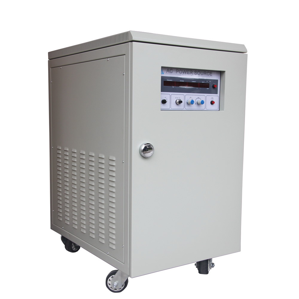
Frequency Conversion: An In-depth Exploration of Technology, Applications, and Market Trends
Click: 995 Date: 02/22/2024 4::09::11 PM
Frequency Conversion: An In-depth Exploration of Technology, Applications, and Market TrendsUnderstanding the Basics of Frequency Conversion: This section could cover the fundamental concepts of frequency conversion, including the need for frequency conversion and the basic principles behind it.Understanding Frequency Conversion BasicsFrequency conversion is a critical concept that spans across various fields, including electronics, telecommunications, and computer technology. It involves the transformation of oscillations or vibrations from one frequency range to another, allowing for accurate measurement, comparison, and optimization of high-frequency systems. The foundational units of frequency, such as hertz (Hz), kilohertz (kHz), megahertz (MHz), and gigahertz (GHz), are essential for precise measurement and analysis. For instance, converting gigahertz (GHz) to hertz (Hz) involves a simple multiplication by one billion, and vice versa, highlighting the direct relationship between these units.The Role of Amplitude and WavelengthTwo key parameters in wave analysis are amplitude and wavelength. Amplitude denotes the maximum displacement of a vibrating object from its equilibrium position, influencing the energy carried by a wave. Wavelength, on the other hand, is the distance between two consecutive points of the same phase on a wave. The relationship between frequency and wavelength is inversely proportional, indicating that as frequency increases, wavelength decreases, and vice versa. This relationship is crucial for understanding the behavior of waves across different frequency ranges.Practical Applications of Frequency ConversionFrequency conversion finds practical applications in fields such as audio engineering, telecommunications, medical imaging, and physics. For example, in audio engineering, converting a musical note to its corresponding frequency is essential for tuning instruments or adjusting audio recordings. In telecommunications, converting frequencies between different bands is necessary for effective signal transmission and reception, especially in satellite communication systems.Importance of Frequency Conversion in Various FieldsThe significance of frequency conversion lies in its ability to transform wave oscillations into a format that can be utilized by various devices and systems. It enables efficient signal transmission, prevents harmful resonance, and aids in the study of wave properties. By converting between different frequency units, we can analyze and manipulate waves for practical applications, emphasizing the importance of frequency conversion in communications, electronics, and physics.Considerations When Converting FrequenciesWhen converting frequencies, such as from gigahertz (GHz) to hertz (Hz), it is crucial to consider the nature of waves, the relationship between frequency and period, and the use of appropriate conversion factors. For instance, understanding that 1 GHz equals 1,000,000,000 Hz is essential for accurate conversion, allowing for a deeper comprehension of frequency and its role in various scientific and engineering applications.Exploring Different Types of Frequency Converters: Here, you would delve into the various types of frequency converters available, such as Voltage Frequency Converters (VFCs), Power Frequency Converters, and Variable Frequency Drives (VFDs), highlighting their unique characteristics and applications.Voltage Frequency Converters (VFCs):VFCs play a crucial role in the power industry, supporting the entire power generation process. They are instrumental in wind power generation, hydropower generation, coal-fired power generation, garbage cleaning, and exhaust gas transmission. VFCs adjust the frequency of the electrical power supply to control motor speed and torque, ensuring smooth operation and energy efficiency.Power Frequency Converters:Power Frequency Converters are designed for use in the oil and gas drilling industry, where they are applied to load-type motors such as gas compressors, water injection pumps, pumping units, oil transfer pumps, and submersible pumps. These converters significantly reduce energy consumption and emissions, making them an essential tool for environmental protection and energy conservation.Variable Frequency Drives (VFDs):VFDs are a type of motor controller that offers precise control over motor speed and torque by adjusting the frequency and voltage of the power supply. They are widely used in applications where speed control and energy efficiency are critical, including HVAC systems, industrial machinery, pumps, and fans. VFDs provide features such as soft start/stop, overload protection, and various control modes, making them ideal for applications that require precise and dynamic speed regulation.General Frequency Converter:General Frequency Converters are versatile and can be used with ordinary cage-type asynchronous motors, adapting to various loads of different nature. They offer a variety of optional functions, making them suitable for a wide range of applications.High-performance Dedicated Frequency Inverter:High-performance dedicated inverters are primarily used in systems with higher requirements for motor control. They typically adopt vector control mode and are designed to drive special motors specified by the inverter manufacturer, ensuring high performance and efficiency.High-frequency Inverter:High-frequency inverters are used in ultra-precision machining and high-performance machinery, where high-speed motors are often required. These inverters adopt the PAM (Pulse Amplitude Modulation) control mode, allowing for the output frequency of the frequency inverter to reach 3kHz, meeting the driving requirements of high-speed motors.IGBT Frequency Inverter:IGBT frequency inverters utilize insulated gate bipolar transistors (IGBTs) as power-switching devices. IGBTs offer high voltage tolerance and high switching speeds, making these inverters ideal for high-power applications. They are widely used in industrial drives and motor control for efficient power conversion.MOSFET Frequency Inverters:MOSFET frequency converters use metal-oxide-semiconductor field-effect transistors as the power-switching device. MOSFETs are known for their low on-resistance and fast switching characteristics, making these frequency converters suitable for applications that require high-frequency switching. They are typically used in low-power applications and high-frequency applications.Each type of frequency converter has its unique characteristics and applications, catering to the specific needs of various industries and applications. Understanding these differences is crucial for selecting the most appropriate frequency converter for a particular application, ensuring optimal performance, energy efficiency, and environmental sustainability.The technological advancements and innovations in frequency conversion are rapidly evolving, with new methods and technologies emerging that promise to enhance efficiency, reduce costs, and improve the performance of frequency conversion systems. Here's an exploration of some of the latest developments in this field:Advancements in Frequency Conversion Technology: The evolution of frequency conversion technology is marked by a shift towards more efficient and compact designs. Innovations in semiconductor materials and power electronics have led to the development of more compact and efficient converters. This has opened up new possibilities for integrating frequency conversion functions into various applications, including renewable energy systems and industrial automation.Digital Control Techniques: The integration of digital control techniques into frequency conversion systems has significantly improved their performance. These techniques allow for precise control over the conversion process, leading to better efficiency, reduced harmonic distortion, and improved reliability. The use of digital signal processing (DSP) algorithms for controlling the converter operation has become a standard practice in modern frequency conversion systemsEmerging Technologies in Frequency Conversion: The field of frequency conversion is not only limited to traditional technologies like power inverters and variable frequency drives (VFDs). Emerging technologies such as solid-state drives (SSDs) and energy harvesting systems are being explored for their potential to enhance the efficiency and performance of frequency conversion systems. For instance, SSDs could offer a more compact and efficient solution for motor control applications, while energy harvesting systems could enable the integration of renewable energy sources into frequency conversion systemsInternet of Things (IoT) Applications: The integration of frequency conversion systems into the IoT is another area of innovation. By connecting frequency converters to the internet, it is possible to monitor and control their operation remotely. This opens up new possibilities for the integration of frequency conversion systems into smart grids and energy management systems, enabling more efficient and flexible energy distributionSpace-Based IoT for Global Connectivity: The use of space-based IoT systems to enhance global connectivity is another innovative application of frequency conversion technology. The deployment of low-cost, low-weight nanosatellites can provide coverage in areas that are currently underserved by terrestrial networks. This technology can be particularly useful for applications that require reliable and high-speed communication, such as remote monitoring and control systems for renewable energy installationsIn conclusion, the technological aspects and innovations in frequency conversion are characterized by a shift towards more efficient, compact, and intelligent systems. The integration of digital control techniques, the exploration of emerging technologies, and the potential for IoT applications all point to a future where frequency conversion systems will play a crucial role in enabling the efficient use of renewable energy sources and the development of smart, connected infrastructures.Frequency converters play a pivotal role across various industries, enhancing efficiency, reducing energy consumption, and improving the performance of electrical systems. Here's a detailed exploration of their applications:Power Generation: Frequency converters are integral to the power industry, where they are utilized in wind power generation, hydropower generation, and coal-fired power generation. Their ability to regulate the speed of AC motors ensures efficient operation of turbines and generators, contributing to the reliability and sustainability of power supply Oil and Gas Drilling: In the oil and gas sector, frequency converters are applied to load-type motors such as gas compressors, water injection pumps, pumping units, oil transfer pumps, and submersible pumps. These applications significantly reduce energy consumption and emissions, aligning with the industry's focus on environmental protection and operational efficiencyBuilding Materials Industry: The building materials industry relies on frequency converters for motors driving crushers, blowers, exhaust fans, rotary kilns, and conveyors. As environmental protection, energy conservation, and emission reduction become priorities, the demand for high-power inverters is on the rise, highlighting the role of frequency converters in driving industry advancementsCoal Industry: In the coal sector, frequency converters are used in mine hoists to improve automation levels, enhance transmission capacity, and reduce electric energy consumption. This application underscores the technology's ability to optimize energy use in mining operationsAutomation Control and Precise Speed Control: Frequency converters offer adaptability and precise speed control, essential for many industrial applications. Their ability to dynamically adjust motor speeds to meet varying load requirements enhances system flexibility and performance. This is particularly critical in machining, production, and transportation processes requiring high precision, such as in robotics on production lines, medical equipment, and laboratory instrumentsThe market for frequency converters is experiencing significant growth, driven by a variety of factors including industrial applications, the need for efficient electrical equipment, and advancements in infrastructure such as high-speed rail systems. The increasing demand for advanced technology, particularly in developing countries, is also a key driver. Additionally, the rise of IIoT (Industrial Internet of Things) is expected to further boost demand across several end-user industries.The global frequency converter market is projected to cross USD 25 billion by 2026, growing at a CAGR of 5% during 2020-2026. This growth is attributed to the expanding industrial sector, investments in infrastructure development, and the integration of IoT technologies. The market is segmented by product type (static and rotary), sales channel (direct and indirect), and end-user industry (food & beverage, aerospace & defense, HVAC, pharmaceutical, marine, metal & mining, chemicals, oil & gas, power generation, packaging, cement, textile, water & wastewater, paper & pulp, rubber & plastic, forestry & woodwork, and others).Key players in the market include ABB, Aplab, Bosch, Danfoss, and Siemens, who are recognized for their innovations in technology, product lines, marketing strategies, and sales networks. The market is also influenced by geographical trends, with different regions showing varying growth rates due to local economic conditions, government policies, and technological advancements.In summary, the future of the frequency converter market looks promising, with continuous growth anticipated in the coming years. This growth is fueled by a combination of technological advancements, increasing demand from various industries, and the global push towards efficiency and sustainability in electrical systems.
Comprehensive Guide to Frequency Conversion Technologies
Click: 861 Date: 02/21/2024 5::33::21 PM
Comprehensive Guide to Frequency Conversion TechnologiesUnderstanding the Basics of Frequency Conversion:Frequency converters play a pivotal role in electrical systems by transforming the frequency of an electrical signal, which is essential for the functioning of various devices and systems.The significance of frequency conversion in power distribution cannot be overstated, as it ensures the stability of the power grid and the reliability of power supply to end-users.Exploring the role of frequency converters in electrical systems:Frequency converters are integral to the operation of electrical systems, enabling the control of devices such as motors and pumps by adjusting the frequency of the electrical supply.They are a key component in the field of power electronics, where they are used to convert and regulate electrical power between different frequency ranges.The importance of frequency conversion in power distribution:Frequency conversion is critical in power distribution as it ensures the stability of the power grid by maintaining a consistent frequency of power supply to consumers.It helps in managing the energy supply effectively, particularly during times of imbalance between generation and load, by allowing for adjustments that can stabilize the power system.AC to DC Converters: Key Features and DesignExploring the role of AC to DC converters in power electronics.The conversion process from alternating current to direct current.The use of transformers to adjust AC voltage levels for DC operation.DC to AC Converters: Operation and UsageThe principles behind DC to AC conversion and its significance in electronic devices.The types of rectifiers and their functions in converting DC to AC.The importance of filters and regulators in ensuring stable DC output.Applications of AC to DC ConvertersThe widespread use of AC to DC converters in household appliances and electronics.The role of AC to DC converters in powering various devices, from small appliances to industrial machinery.The applications of AC to DC converters in renewable energy systems and telecommunications.Emerging Trends in AC-DC ConvertersThe development of new materials like GaN and SiC for more efficient converters.The trend towards compact and reliable AC-DC converters for improved energy efficiency.The integration of renewable energy systems with the help of advanced AC-DC converters.Conclusion: The Future of AC-DC ConvertersThe evolution of AC-DC converters from linear power supplies to switched-mode power supplies.The importance of understanding AC-DC converter design for future innovations.The potential for more efficient and sustainable power solutions through advancements in AC-DC technology.Inverters are an advanced frequency conversion technology that play a crucial role in renewable energy systems. They convert direct current (DC) from solar panels or wind turbines into alternating current (AC), which can be used by households, businesses, and the grid. This conversion is essential because while renewable energy sources generate DC, most appliances and systems require AC to operate.Frequency transformers are another critical component in power quality improvement. They help to regulate the frequency of the power supply, which is particularly important in systems that use variable frequency drives or renewable energy sources. By adjusting the frequency, frequency transformers can ensure that the power supply remains stable and within acceptable limits, thus preventing issues such as overheating or damage to electrical equipment.In the context of renewable energy, frequency transformers can also assist in managing the variable output of wind turbines and solar panels, which can fluctuate based on weather conditions and time of day. This stability is essential for maintaining a reliable power supply, especially as these sources become more integrated into the power grid.In summary, inverters and frequency transformers are key technologies in advanced frequency conversion that enable the integration of renewable energy sources into the power grid. They ensure that the variable and fluctuating nature of renewable energy can be effectively managed and converted into a stable and usable form of power.In the realm of power electronics, voltage regulation is a critical concept when it comes to frequency converters. Voltage regulation ensures that the output voltage of the converter remains stable despite variations in the input voltage or load conditions. This is achieved through the use of regulatory components such as voltage regulators or voltage-sensitive capacitors, which adjust the output voltage to maintain a consistent level.Harmonic filters play a pivotal role in the process of power factor correction. Power factor correction is essential for reducing power losses in electrical systems, as it minimizes the phase difference between the voltage and current waveforms. Harmonic filters, specifically designed to target specific harmonic frequencies, can suppress these distortions, thereby improving the power factor. They are typically composed of inductive and capacitive elements that create resonance at the desired harmonic frequency, effectively shunting the harmonic currents away from the load and reducing the overall harmonic distortion in the system.The impact of harmonic filters on power factor correction is significant, as they can prevent equipment misoperation, reduce the likelihood of capacitor bank failure, and prevent unexpected tripping of circuit breakers. By mitigating harmonic distortions, harmonic filters contribute to the overall power quality of the system, which is a key consideration for the safe and efficient operation of electrical equipment.Design and Implementation of Frequency ConvertersThe essence of designing frequency converters involves understanding the principles of power electronics and the specifics of power factor correction within electronic circuits.The design process for frequency converters must consider the challenges of achieving high energy efficiency, which includes managing the power factor to avoid additional costs and potential overheating issues in electrical systems.Principles of Power Factor Correction in Electronic CircuitsPower factor correction is essential for maintaining the efficiency of power systems, as it involves the balance between real power (P) and apparent power (S), with power factor (pf) being the ratio of P to S.The power factor is crucial because it affects the cost of electricity, the lifetime of electrical equipment, and the sizing of accessories like cables. A power factor close to unity is ideal for minimizing these issues.Challenges and Solutions in Designing Power Electronics for High Energy EfficiencyAchieving a high power factor is a key objective for power electronics design, as it can lead to significant cost savings and reduced energy consumption.The design of power electronics must account for the effects of low power factors, such as increased costs for power utilities and potential overheating risks for electrical components.To address these challenges, power electronics designers must implement power factor correction methods, such as using capacitor banks or synchronous condensers, to compensate for reactive power and improve the overall efficiency of the system.
Comprehensive Guide to 19-Inch DC-DC Converters: Technology, Applications, and Design
Click: 1129 Date: 02/19/2024 3::33::50 PM
Comprehensive Guide to 19-Inch DC-DC Converters: Technology, Applications, and Design19-inch DC-DC converters are a specific type of power converter that are commonly used in various applications, including computer power supplies, automotive electronics, and industrial machinery. These converters are designed to transform direct current (DC) from one voltage level to another, ensuring that electronic devices receive the appropriate power supply needed for their operation.DC-DC converters play a crucial role in power electronics by enabling the efficient conversion of DC power. They are particularly important in systems where the input voltage does not match the voltage requirements of the components, such as in portable devices like laptops and smartphones. By stepping up or stepping down the voltage, DC-DC converters ensure that the device operates within its voltage tolerances, thereby preventing damage to the components and extending the life of the device.The operation of a 19-inch DC-DC converter involves a series of electronic components that control the flow of current and the conversion of voltage. The key components of a DC-DC converter include a switch, which controls the flow of current, and a filter, which removes any unwanted noise or distortion from the output voltage. These components work together to convert the input voltage to a regulated output voltage, which is then used by the electronic device.In practice, DC-DC converters are designed to be highly efficient, with efficiencies typically ranging from 70% to 95%. This efficiency is achieved through the use of switched-mode power conversion techniques, which minimize power loss and reduce the need for cooling. The use of high-frequency switching and pulse-width modulation (PWM) allows for precise control over the output voltage, which is crucial for maintaining the performance and reliability of the electronic device.The history of DC-DC converters dates back to the early stages of semiconductor technology, where power conversion was achieved by converting DC to AC and then back to DC using transformers and rectifiers. With the advent of integrated circuits and solid-state components, the design and implementation of DC-DC converters have become more efficient and cost-effective, making them an indispensable part of modern power electronics.Buck, Boost, and Buck-Boost ConvertersBuck converters are DC-to-DC power converters that reduce voltage from the source to the load by drawing a smaller average current. They are particularly efficient, often exceeding 90%, making them suitable for converting high-voltage power supplies to lower voltages required by devices such as USB, DRAM, and CPUs .Boost converters, on the other hand, are used to increase the voltage from the source to the load. They are often employed in applications where a higher voltage is needed, such as in battery-powered devices or solar chargers .The buck-boost converter is a versatile DC-to-DC converter that can either increase or decrease the voltage from the source to the load. This versatility makes it a popular choice for applications that require a wide range of output voltages .SEPIC Converters and Their ApplicationsSEPIC (Switched Energy Packet Injection Converter) converters are a type of DC-to-DC converter that can operate in both buck and boost modes. They are known for their high efficiency and wide input voltage range, which makes them suitable for a variety of power management applications .SEPIC converters are often used in battery-powered devices and renewable energy systems where they can provide a constant output voltage regardless of the input voltage fluctuations. They are also used in applications that require a wide range of output voltages, such as in electric vehicles or renewable energy systems .The use of SEPIC converters in such applications is advantageous because they can handle a wide range of input voltages and maintain a constant output voltage, which is crucial for the stable operation of electronic devices and systems .Maximizing Power Conversion EfficiencyHigh-efficiency DC-DC converters are essential for reducing energy costs and environmental impact.Efficient converters minimize power losses, leading to lower electricity bills, especially in high-demand environments.High-efficiency converters can also extend the lifespan of electronic devices by reducing heat generation, which is a major cause of wear and tear.Thermal Management in DC-DC ConvertersThe efficiency of a DC-DC converter is influenced by the amount of heat it generates.Converters with higher efficiency produce less heat, which can extend the durability of the converter and the devices it powers.The need for additional cooling systems is reduced with improved efficiency, which helps conserve energy and reduce environmental impact.Optimizing Power Supply SystemsThe efficiency of a DC-DC converter is a critical metric for determining the performance of power supply systems.A highly efficient converter ensures that the majority of input energy is converted to output energy, minimizing energy loss.The efficiency of a DC-DC converter can vary based on factors such as input and output voltage levels, load current, and the quality of the converter's components.Considerations for Efficient Power SupplyWhen selecting a DC-DC converter, it's important to consider factors beyond efficiency, such as form factor, thermal management, and cost.Efficient converters contribute to energy-efficient practices and environmental sustainability.Understanding how to measure and identify the highest-efficiency converters in the market is essential for making informed decisions.DC-DC converters have a broad spectrum of applications in various industries. They are integral to industrial automation systems, where they power and control various components, ensuring a stable and regulated power supply, which is crucial for the efficiency and reliability of industrial processes. In the automotive industry, DC-DC converters are used to convert high-voltage DC power from the traction battery to the lower voltages required by vehicle systems and components.In the telecommunications sector, DC-DC converters are essential for powering communication devices, base stations, routers, and switches, facilitating voltage conversion and regulating the power supply to ensure reliable operation. In the military and aerospace domains, DC-DC converters are employed to regulate and convert power in avionics systems, satellite communication systems, military equipment, and radar systems, providing reliable power supply and voltage conversion in demanding environments.Moreover, in renewable energy systems such as solar power and wind turbines, DC-DC converters are critical for optimizing power generation by converting and regulating the variable DC output voltage from solar panels or wind generators to match the required voltage level for grid integration or battery charging. Lastly, in data centers, DC-DC converters are used to regulate and distribute power to servers, networking equipment, storage systems, and cooling infrastructure, ensuring efficient power conversion, voltage regulation, and overall energy optimization.These applications underscore the versatility and importance of DC-DC converters in modern technology, where they are used to manage and optimize power distribution across a wide range of devices and systems.When designing and implementing DC-DC converters, several key considerations must be taken into account to ensure safety and optimal performance. These include:Insulation Ratings: It is crucial to select a DC-DC converter with appropriate insulation ratings to prevent electrical shocks and short circuits. The insulation grade should be high enough to withstand the operating conditions of the device .Safety Standards Compliance: DC-DC converters must meet specific safety standards to ensure they are safe to use. This includes adherence to standards such as EN60950-1 and UL60950-1, which dictate temperature limits and thermal insulation requirements .Thermal Management: Overheating is a common issue with DC-DC converters, especially those that convert high power levels. To prevent this, thermal management strategies such as heat sinks, thermal insulation, and effective heat dissipation methods must be incorporated into the design. This can involve using MOSFET transistors with lower static drain-to-source on-resistance or designing PCBs with wide parallel traces and numerous vias to facilitate heat dissipation 4.Power Electronics Design: The design process for DC-DC converters involves both hardware and software components. Hardware design includes selecting the appropriate components and arranging them to achieve the desired voltage conversion. Firmware development focuses on creating control algorithms to manage the converter's operation and optimize its performance .Package Selection: The choice of packaging for DC-DC converters can affect the device's overall size, mounting style, and thermal performance. Designers must select a package that fits the application's requirements and can accommodate the thermal management solutions needed to prevent overheating .By addressing these design and safety considerations, engineers can create DC-DC converters that are not only efficient but also reliable and safe for use in a wide range of applications.
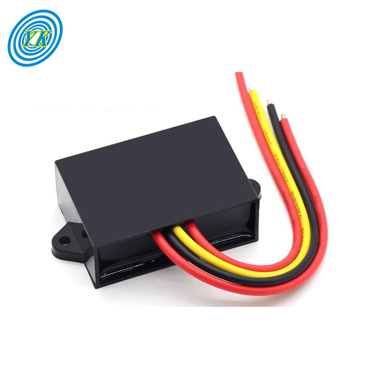
Comprehensive Guide to Buck/Boost DC-DC Converter Design
Click: 923 Date: 02/18/2024 3::24::54 PM
https://www.yucoo.com/detail.php?id=883Comprehensive Guide to Buck/Boost DC-DC Converter DesignWhen designing a Buck/Boost converter, it's essential to understand the fundamental principles of operation and the key components involved. Here's a breakdown of the design process:Understanding the Buck/Boost Converter: The Buck/Boost converter is a DC-to-DC converter that can either increase or decrease the input voltage, or both. It operates by switching a transistor on and off to control the flow of current through an inductor, which stores and releases energy to regulate the output voltage.Continuous Mode Operation: In continuous mode, the inductor current is maintained constant during the off-state, and the output voltage's polarity is opposite to the input. The output voltage can theoretically range from zero to negative infinity, depending on the duty cycle of the switching transistor .Effect of Parasitic Resistances: Parasitic resistances within the converter circuit, such as the inductor's resistance, can affect the voltage gain and the efficiency of the converter. As the inductor resistance increases, the voltage gain decreases, which can impact the performance of the converter .Inverting and Non-Inverting Topologies: The inverting topology has an output voltage with the opposite polarity to the input, while the non-inverting topology maintains the same polarity. The non-inverting Buck/Boost converter can use a single inductor for both the buck and boost modes, with switches replacing diodes .Principle of Operation: The converter works on the principle of energy storage in the inductor during the on-state and energy transfer to the load during the off-state. The duty cycle of the switching transistor determines the output voltage magnitude .Conceptual Overview: The inductor's "reluctance" to allow rapid changes in current is central to the operation of the converter. The inductor stores energy in a magnetic field when the switch is closed, and releases this energy when the switch is open .Four-Switch Topology: This topology combines the buck and boost converters, with one switch controlling the duty cycle and another for commutation. The remaining two switches are in a fixed position. This design can improve efficiency and reduce voltage drop .Transfer Functions: The transfer functions for the buck, boost, and buck-boost converters are crucial for understanding the control-to-output and line-to-output characteristics. These functions can help in designing feedback control systems to stabilize the converter.Converter Circuit Topologies: There are various topologies for DC-DC converters, each with its conversion ratio and method of operation. The buck converter reduces voltage, the boost converter increases it, and the buck-boost converter can do both.Transformer Isolation: Transformer isolation is a common method to incorporate in any DC-DC converter for safety and noise reduction. The flyback converter is an isolated version of the buck-boost converter, which is widely used in high-voltage power supplies By understanding these principles and applying them in the design process, you can create a Buck/Boost converter that meets the required performance specifications.Switching power supply techniques are integral to the operation of Buck/Boost converters, which are used to step up or step down voltage levels. These techniques include:Buck Mode: In this mode, one switch is always ON, and the other is OFF. The output voltage is regulated by controlling the duty cycle of the ON switch. Buck mode is efficient when the input voltage is higher than the output voltage, as it minimizes power dissipation and stress on the components.Boost Mode: Here, the switches are operated in reverse, with one switch always OFF and the other ON. The output voltage is regulated by controlling the duty cycle of the ON switch. Boost mode is efficient when the input voltage is lower than the output voltage, reducing the number of operating power devices and current stress.Buck-Boost Mode: This mode combines the operation of both Buck and Boost modes. The converter operates in Buck mode when the input voltage is higher than the output voltage and in Boost mode when the input voltage is lower than the output voltage. The efficiency of Buck-Boost mode is generally lower than either Buck or Boost mode alone, but it can achieve high efficiency over a wide input voltage range.Transition Mode: In this mode, the converter operates between Buck and Boost modes, transitioning between them to maintain efficiency. This mode is particularly useful when the input voltage varies significantly, allowing the converter to adapt to the changing conditions.Control Circuitry: To optimize the efficiency and performance of a Buck/Boost converter, appropriate control circuitry is required. This circuitry manages the switching of the power MOSFETs and diodes, ensuring the converter operates in the most efficient mode based on the input and output voltage conditions.The choice of switching technique and control circuitry design can significantly impact the efficiency and performance of a Buck/Boost converter. For instance, the two-switch Buck-Boost converter, which can function in Buck-Boost, Buck, or Boost modes, demonstrates the versatility of these techniques. The control complexity varies, with Buck-Boost mode offering the simplest control but lower efficiency, while the combination of Buck and Buck-Boost modes provides a balance between control complexity and efficiency.In summary, the different switching techniques in Buck/Boost converters, such as Buck mode, Boost mode, Buck-Boost mode, and transition mode, are tailored to optimize performance and efficiency under various input voltage conditions. The design of the control circuitry is crucial in managing these modes and ensuring the converter operates in the most suitable mode for the given application.Efficiency optimization and thermal management are key aspects of Buck/Boost converter design to ensure reliable operation and longevity. Here are some strategies for enhancing efficiency and managing heat in these converters:Minimize Inductor Losses: Inductor losses do not directly raise the IC temperature, but they do contribute to heat generation. By using inductors with lower losses or lower bias current, the overall heat generation can be reduced. This can be achieved by selecting appropriate inductors based on their specifications and power conditions .FET Temperature Coefficient: The temperature coefficient of the FET in the converter plays a significant role in its efficiency. As the ambient temperature increases, the FET's on-resistance (RDS(on)) also increases, which can lead to efficiency degradation. It's essential to consider this in the design calculations to ensure the converter operates efficiently at high temperatures .Thermal Optimization at the IC Level: Cooling limitations can affect the thermal performance of the power converter. Adjusting the switching frequency can be a quick fix to reduce power losses and improve thermal performance. However, this must be balanced with device performance and overall cost considerations .PCB Layout and Heat Sinking: The layout of the PCB is a critical factor in the thermal performance of the converter. The effective copper area available for heat sinking directly impacts the thermal resistance between the ambient air and the semiconductor junction on the converter's die. A larger copper area can improve heat dissipation and, consequently, the thermal performance of the converter.Inductor Placement: The placement of the inductor on the PCB can also affect the converter's thermal performance. Inductors with a high DC resistance and a small physical size can cause the inductor to heat up, especially at high output currents. Proper placement and design can help to manage this heat and maintain a balance between thermal performance and EMI noise .Use of Thermal Vias: Thermal vias can be used to enhance the thermal performance of the PCB by providing additional paths for heat to dissipate. However, it's important to use them judiciously to avoid increasing the overall cost and complexity of the PCB design .Switching Frequency Adjustments: Adjusting the switching frequency can have a significant impact on the power losses in the converter. A slower switching frequency can reduce switching losses, which are related to the parasitic FET capacitances and the switching frequency at which they charge and discharge .By implementing these strategies, the efficiency of Buck/Boost converters can be significantly improved, and the risk of thermal-related issues can be mitigated. It's important to consider all these factors in the design phase to ensure a reliable and efficient power conversion system.Protection Circuits and Load Regulation in Buck/Boost ConvertersProtection circuits are vital components of Buck/Boost converters, ensuring the safe operation of the device and the stability of the output voltage. These circuits serve to prevent damage to the converter and the connected load due to adverse conditions such as overvoltage and undervoltage.Overvoltage protection is a critical feature that prevents the output voltage from exceeding the device's maximum rating, which could lead to damage or failure of the output components or even the entire system. For instance, Texas Instruments' TPS63060-EP series includes an overvoltage protection circuit that monitors the output voltage and adjusts it to prevent exceeding critical values.Undervoltage protection is equally important. It prevents the converter from starting up if the input voltage falls below a certain threshold, thereby protecting the device from potential damage from insufficient input power. The TPS63060-EP series also features an undervoltage lockout function that automatically enters shutdown mode if the input voltage drops below a predetermined level.Load regulation is another essential aspect of Buck/Boost converter design. It refers to the ability of the converter to maintain a steady output voltage despite changes in the load current. A well-designed Buck/Boost converter should exhibit minimal change in output voltage with varying load conditions. This is achieved through careful design of the control loop and the selection of appropriate components.In summary, the protection circuits and load regulation are fundamental to the reliable operation of Buck/Boost converters. They safeguard the converter and the connected devices from potential damage due to voltage fluctuations and ensure a stable power supply.To examine the critical aspects of PCB layout design for Buck/Boost converters, you should consider the following points:Component Placement: The placement of components is crucial for the success of a Buck/Boost converter. It is recommended to place the power components as close as possible to the converter IC. This includes the input capacitor, inductor, and output capacitor. These components should be placed on the same surface layer as the IC pins they are connected to to minimize voltage noise and radiated EMI.Routing: Routing should flow naturally from the placement of components. Short, direct traces should be used on critical nets, and bypass capacitors should be cascaded outwards to increase capacitance. The routing should be designed to minimize inductance and ensure proper current return paths, avoiding noisy currents that could affect sensitive circuits.Precision Layout: The layout of the buck converter circuitry must be precise. Parts should be kept close together to minimize connections and monitor how different grounds of the circuit are partitioned. The ground routing should be designed so that current return paths follow a logical progression.Manufacturing Rules: The placement of components must comply with manufacturing rules. For instance, the input capacitor should be placed as close to the IC as allowed by these rules. Planes should be used to connect the input capacitor’s terminals to the IC’s, minimizing trace inductance.Design Tools: Utilize PCB design CAD tools that allow you to set up design rules for different types of power and ground circuits. This will enable you to assign different routing parameters to each network, set up spacing rules, and manage components effectively.EMI Reduction: To reduce radiated EMI, the inductor should be placed close to the IC and on the same board surface layer. This proximity will help to contain the EMI within the converter circuit.Thermal Design: Consider the thermal design of the power stage. The placement of power MOSFETs, wide aspect ratio footprint current shunts, and input and output ceramic capacitors should be strategically planned to ensure optimal switching regulator performance.By adhering to these guidelines, you can create an optimized PCB layout for a Buck/Boost converter that meets specific power and efficiency requirements.