Category
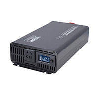
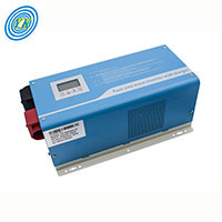
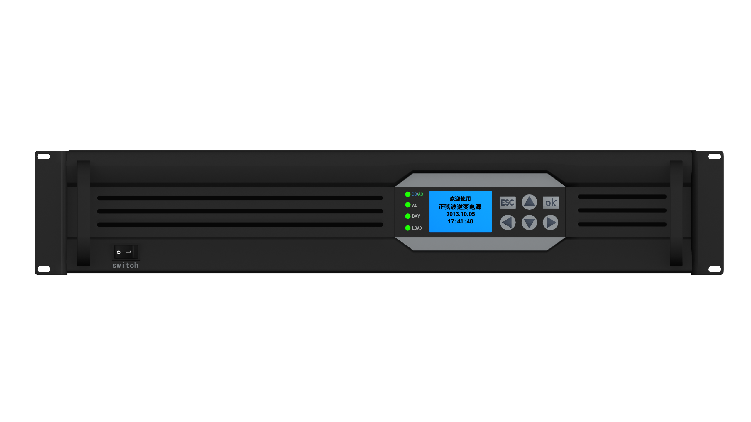
- Pure sine wave Inverter with LCD
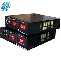
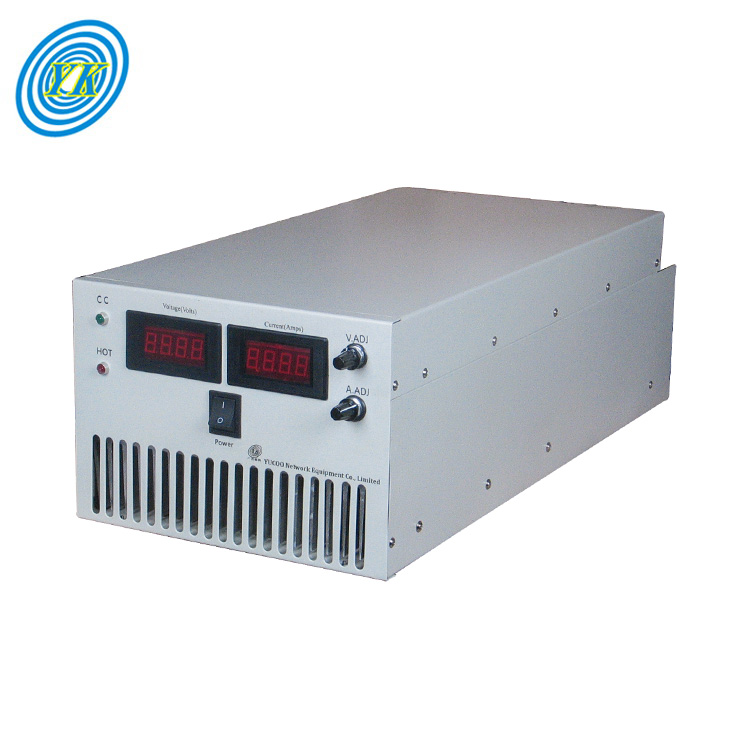
- Adjustable DC Power Supply
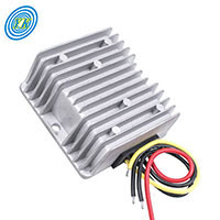
- Buck DC-DC Converter
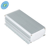
- Boost DC DC Converter
- Buck/Boost DC DC Converter
- New Isolated DC DC Converter
- AC to DC Converter
- Bared Board DC DC Converter
- Low frequency Inverter with Charger
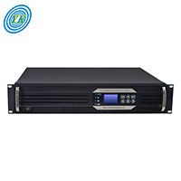
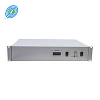
- Telecom Inverter
- 19 inch DC-DC Converter
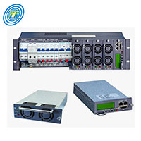
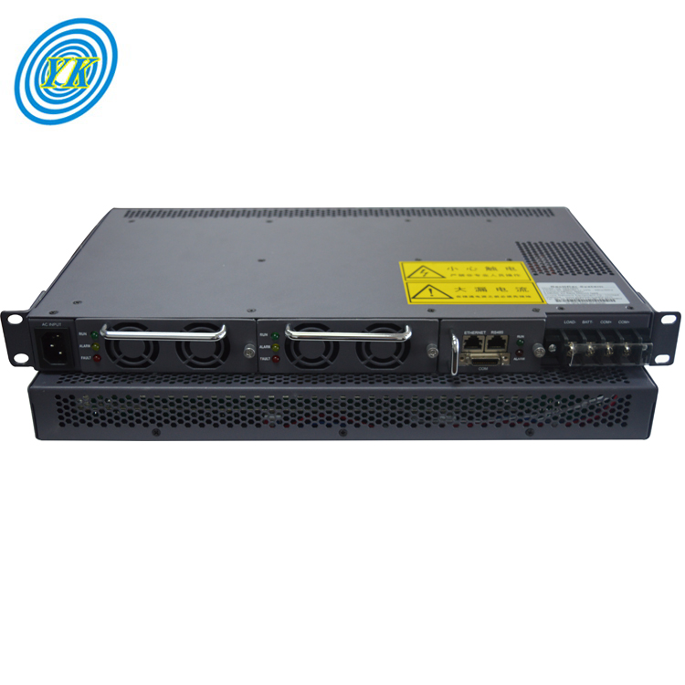
- Rectifier & Rectifier System
- Battery Charger - (Civil use)
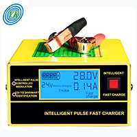
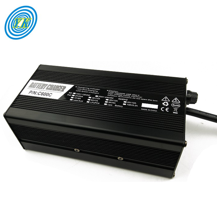
- Battery Charger - (Industry)
- Frequency Converter
- PDU-Power Distribution Unit

- Inverter built-in MPPT
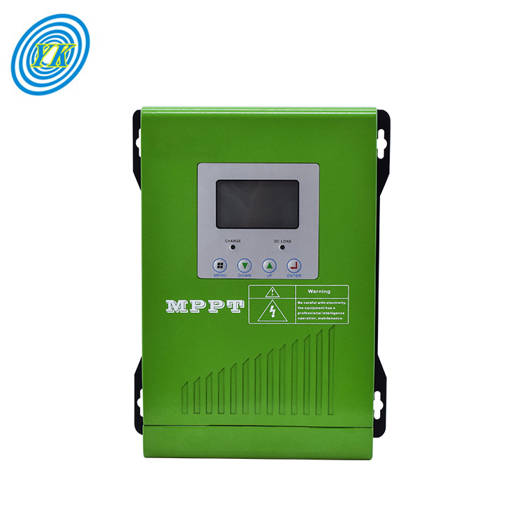
- MPPT Controller
- Portable power station

- Transformer
- Switching Power Supply
- Plating rectifier
Optimizing Telecom Infrastructure: Inverters, Power Systems, and Renewable Integration
Click: 875 Date: 02/05/2024 4::44::01 PM
Optimizing Telecom Infrastructure: Inverters, Power Systems, and Renewable IntegrationInverters play a crucial role in telecom power systems by transforming direct current (DC) power into alternating current (AC) power. This conversion is vital because most telecom equipment operates on AC power. Inverters are fundamental components of modern electrical systems, including those found in telecommunications, where they ensure that the power supply remains stable and reliable.Different types of inverters exist, each designed for specific applications. For instance, grid tie inverters are commonly used in solar power systems to feed excess power back to the grid. Similarly, uninterruptible power supplies (UPS) with built-in inverters provide emergency power to critical telecom equipment during power outages. These inverters are essential for maintaining continuous communication services during unexpected power disruptions.Moreover, microinverters are increasingly being adopted in telecom applications due to their compact size and efficiency. They allow for the integration of renewable energy sources like solar panels directly into telecom infrastructure, offering sustainable power solutions. This approach reduces reliance on traditional power grids and contributes to environmental conservation.In summary, understanding the role of inverters in telecom power systems is paramount for ensuring the reliability, efficiency, and sustainability of telecommunications infrastructure.Inverter technologies have a profound impact on sustainable power solutions, transforming the way we harness and distribute energy. Here are some insights into how inverters contribute to sustainability:Cost-Effectiveness: Inverters provide a financially viable alternative to traditional power generation methods, particularly as the costs of renewables like solar panels continue to decline.Reliability: Advanced monitoring and safety features inherent in inverters ensure a consistent and secure energy supply, which is essential for the stability of the power system.Clean Energy Production: Inverters facilitate the conversion of renewable energy sources, thereby reducing reliance on fossil fuels and minimizing harmful emissions.Scalability: The scalability of inverters allows for expansion of energy capacity as demand grows, making them suitable for both residential and commercial sectors.Grid Integration: Inverters can be seamlessly incorporated into the existing power grid, facilitating a gradual shift towards a more sustainable energy infrastructure.Moreover, inverters play a crucial role in the evolution of the power system, improving efficiency and enabling decentralization. They are instrumental in integrating renewable energy sources, reducing the need for large power plants, and lowering the environmental footprint of energy production. Additionally, inverters empower individuals and businesses by offering greater control over energy generation and usage, fostering a more democratic energy landscape.Technological advancements are further enhancing the capabilities of inverters, leading to increased efficiency and cost reduction. Integration of digital technology into inverters, such as advanced monitoring systems and smart grid capabilities, is a significant trend shaping the future of inverters. These developments not only optimize energy generation and consumption but also ensure a stable and reliable supply of electricity.In summary, inverter technologies are a cornerstone of sustainable power solutions, offering a multifaceted approach to energy production, distribution, and management. As the world moves towards greener energy practices, the importance of inverter technologies in achieving a cleaner and more efficient power system will only continue to grow.Integrating Renewable Energy: The Use of Solar Inverters in Telecom involves leveraging solar technology to provide power to telecommunication facilities. Here are some key points to consider:Solar Energy and Telecom: The adoption of solar inverters in telecom infrastructure is part of a broader trend towards renewable energy sources, aiming to reduce carbon emissions and increase energy independence.Benefits of Solar Inverters: Utilizing solar inverters offers several advantages, including sustainability, energy independence, cost savings, and improved reliability. They enable telecom installations to become self-sufficient in power and reduce their dependency on external power providers.Government Incentives: Governments are encouraging the adoption of renewable energy in telecom through incentives like tax benefits and subsidies, which can further boost the cost efficiency of solar inverters.Reputation Enhancement: Adopting solar inverters can improve a company's public image, positioning them as environmentally responsible and forward-thinking.Reduced Carbon Footprint: Telecom facilities powered by solar energy emit significantly fewer greenhouse gases compared to those using traditional generators, contributing to climate change mitigation efforts.By integrating solar inverters into telecom power systems, operators can achieve a cleaner, more sustainable operation that also potentially leads to economic benefits.Uninterruptible Power Supplies (UPS) play a crucial role in telecommunications by ensuring continuous power availability and minimizing downtime. Here's a rephrased discussion on the importance of UPS in telecommunications:UPS systems are essential components of telecommunication infrastructure, serving as the backbone of reliable power delivery. They are designed to provide instantaneous, fail-safe power to critical systems in the event of a power outage, thus preventing service interruptions and ensuring business continuity.Telecommunication networks must remain operational without exception, particularly considering the reliance of sectors like healthcare and defense. To achieve this, it is vital to understand the potential threats to power supply and implement effective mitigation strategies. These strategies may involve robust internal security measures, advanced sensor technology, battery backups, and having spare parts readily available.Emergency power solutions like generators and UPS systems are designed to operate under extreme conditions, delivering consistent performance regardless of weather events or human errors. Specialized UPS products, such as those offered by Dale Power Solutions, are equipped to withstand such challenges, providing a reliable power source that maintains the integrity of telecommunication services.For UPS systems to function optimally, they should be adequately loaded to reach their full efficiency. Most UPS manufacturers recommend that the UPS should be at least 30% loaded to avoid compatibility issues and ensure proper operation. Additionally, the use of a network management card can facilitate monitoring functions, allowing for timely notifications to customers regarding UPS status.In the case of large UPS systems, such as those built up from smaller units (e.g., 250kW), the UPS will respond to a failure by removing the failed unit from the load while the remaining power cabinets continue to carry the load. This modular approach ensures that the entire system remains functional and continues to provide power.Maintenance procedures, such as static bypass for emergency operations and maintenance bypass for planned events, are integral to keeping UPS systems in peak condition. It is also recommended to keep UPS systems in a controlled environment to preserve the longevity of the batteries.In summary, UPS systems are indispensable in telecommunications for their ability to maintain power supply continuity, support emergency operations, and ensure the smooth functioning of critical telecom services.Microinverters play a crucial role in ensuring reliable communications by providing stable and efficient power conversion. They are particularly important in grid support and frequency control, which are critical for maintaining grid stability and preventing voltage fluctuations that could lead to communication interruptions.Control strategies for microinverters can vary widely, depending on whether they are operating in grid-connected mode, islanding mode (off-grid), or even with reactive power compensation. When microinverters are part of a hybrid system, they can be controlled to limit their output and achieve zero export to the grid when necessary. This is achieved by using a relay or other switching mechanisms that allow the microinverters to be turned on and off as required.In situations where the load is smaller than the production capacity of the microinverters, especially when they are on the grid, the hybrid inverter may try to absorb the excess production by driving the AC charger to store excess AC-coupled production. However, this approach becomes less effective as the battery approaches full charge, leading to increased export to the grid.Hybrid inverters have the ability to control frequency shift and microinverter output when off the grid to match production to load. However, when on the grid, if the load is smaller than the AC-coupled microinverter production, the hybrid inverter's ability to control the output is limited.Despite these complexities, there are methods available to manage microinverters effectively. For instance, the Envoy S Meter can control Enphase Microinverters, offering users the ability to regulate their performance and maintain optimal grid support. Furthermore, some hybrid or All-In-One (AIO) systems can throttle microinverter output when not off the grid, helping to balance production with demand.In summary, microinverters are essential components in telecom power systems, providing key support for grid operations and frequency control. Their integration into hybrid systems allows for advanced control strategies, including frequency shifting and output throttling, which are vital for achieving reliable communications and maintaining grid stability.
Designing and Simulating a Pure Sine Wave Inverter with LCD using Key Components and Tools
Click: 884 Date: 02/02/2024 10::30::45 AM
Designing and Simulating a Pure Sine Wave Inverter with LCD using Key Components and ToolsMicrocontrollers play a crucial role in the operation of pure sine wave inverters. They are responsible for controlling the switching signals that drive the H-bridge circuit, which in turn generates the output AC signal. The microcontroller's job is to interpret user input, such as adjusting voltage or frequency, and translate these commands into the correct switching pattern to produce the desired output.The process begins with the microcontroller receiving input from the user through an interface, typically an LCD display. This input is then processed and converted into instructions for the H-bridge circuit. The microcontroller uses its internal clock to generate timing pulses, which determine when the switches in the H-bridge circuit should open and close.By controlling the timing of the switches, the microcontroller effectively controls the shape of the output waveform. It ensures that the output remains a pure sine wave, free from harmonic distortion. This is achieved by using a low pass LC filter, which removes high frequency components from the output signal, leaving only the fundamental frequency intact.The microcontroller also manages the power supply to the inverter. It monitors the voltage levels and adjusts them as needed to ensure stable operation. Furthermore, it provides feedback to the user through the LCD display, allowing them to monitor the performance of the inverter and make any necessary adjustments.In conclusion, the microcontroller is a vital component in a pure sine wave inverter. Its ability to control the operation of the H-bridge circuit and manage the power supply makes it indispensable for producing clean, efficient AC power from DC input.Switching signals play a crucial role in the operation of inverters, particularly in power conversion processes. These signals, generated by microcontrollers, dictate the switching of electronic switches within the inverter. This switching process allows the inverter to convert direct current (DC) into alternating current (AC), enabling devices that require AC to operate properly.In a pure sine wave inverter, the switching signal is essential for producing a smooth, continuous waveform. Without a well-timed and precise switching signal, the output could be distorted, leading to poor performance in connected devices. Therefore, the quality and timing of the switching signal directly impact the efficiency and reliability of the inverter.Moreover, the frequency and duty cycle of the switching signal can affect the voltage regulation capabilities of the inverter. A higher frequency can lead to a more efficient conversion process, while a suitable duty cycle ensures that the output remains within acceptable limits.In summary, the switching signal is a vital component in the operation of an inverter. It controls the switching of electronic switches, determines the output waveform, and influences the overall performance of the device. Therefore, understanding the importance of switching signals in inverter operation is key to designing effective and reliable inverters.H-bridge circuits play a critical role in power conversion systems. They act as a full bridge rectifier, converting AC power into DC power. This process involves two semiconductors, typically transistors or diodes, connected in such a way that current flow is possible in both directions.In a typical H-bridge configuration, four switches are used. Two of these switches form one half-bridge, while the other two form the second half-bridge. The switches alternate between being on and off, allowing for the control of the direction of current flow.One of the key benefits of H-bridge circuits is their ability to control the direction of current flow. This makes them ideal for applications where the direction of power needs to be reversed, such as in motor control systems.Another advantage of H-bridge circuits is their ability to convert AC power into DC power. This is achieved by rectifying the input AC signal, effectively removing the negative half of the waveform. The result is a pulsating DC output, which can then be smoothed using filtering techniques.In summary, H-bridge circuits are essential components in power conversion systems. Their ability to control current flow and convert AC power into DC power makes them highly versatile and useful in a wide range of applications.Low Pass LC Filters play a crucial role in maintaining pure sine waves in inverters. These filters are integral to the operation of a Uninterruptible Power Supply (UPS), which essentially functions as a switching regulator. The LC filter on a UPS operates at a cut-off frequency significantly lower than the Pulse Width Modulation (PWM) frequency. For instance, if the PWM circuit operates at 100kHz, the filter would have a cut-off frequency of 3 to 5kHz. This design ensures that high frequencies, which can cause significant voltage amplification and potentially damage the transistors, are barely visible on the output, thus reducing emissions.The LC filter's natural resonant frequency remains largely unaffected by load changes, but its damping factor, which is the inverse of the quality factor (Q), adjusts accordingly. As the load increases, the damping factor decreases, leading to underdamping. On the contrary, when the load is minimal, the damping factor increases, resulting in overdamping. It's important to note that these changes in the damping factor can lead to significant voltage amplification if the PWM frequency or harmonic artifacts are close to the cut-off frequency, potentially damaging the transistors.In the context of high-power class-D amplifiers, an LC filter is often applied to the output of the amplifier. This filter is passive and utilizes both an inductor and a capacitor on each output terminal. The proper selection of the LC filter components is essential to achieve the desired audio performance, efficiency, Electromagnetic Compatibility/Interference (EMC/EMI) requirements, and cost for the end application. The frequency response of the LC filter is particularly important when selecting the inductor and capacitor values. The load impedance determines the damping ratio of the output LC filter and is classified as overdamped, critically damped, or underdamped.The LC filter's Q factor or damping ratio is another important consideration when selecting components for the second-order low-pass filter. Texas Instruments (TI) recommends using a second-order Butterworth low-pass filter due to its flat pass-band and phase response. TI advises against the use of LC filters that peak excessively, like the underdamped filter response, as they can be harsh to the human ear and potentially trigger the protection circuitry of some amplifiers. However, overdamped filters can result in the attenuation of high-frequency audio content in the audio band.In conclusion, the LC filter plays a vital role in maintaining pure sine waves in inverters by filtering out high-frequency noise and maintaining the stability of the system. Its design and component selection are crucial for achieving the desired performance and efficiency.
Understanding the Role of Inverters in Solar Power Systems
Click: 1021 Date: 02/01/2024 2::15::09 PM
Understanding the Role of Inverters in Solar Power SystemsThe Crucial Role of Inverters in Converting DC to AC PowerAn inverter serves a pivotal role in a photovoltaic (PV) system and solar energy generation, transforming the DC output of a string of PV modules panel into AC power. This conversion is crucial due to the preference for AC power over DC power. AC power can be amplified in voltage via a transformer more easily than DC and is more cost-effective to transmit over long distances. Furthermore, most electricity grids operate on AC, making it necessary for solar panels that produce DC to convert to AC.Microinverters: A Closer LookMicroinverters, installed on each solar panel, convert DC power to AC power at the panel level, eliminating the need for a string or central inverter. They help mitigate the detrimental effects of shading and prevent a single point of failure within the system. Despite being more expensive in terms of hardware and labor, they create more potential points of failure within the system, hence their rare use in commercial systems.Battery Inverters: A Key ComponentLike solar panels, batteries output DC power and thus require inverters. Unlike solar inverters, battery inverters are typically connected to a site controller that decides when to charge or discharge the batteries. These inverters can operate in both directions, enabling AC power to convert to DC power to charge batteries.Inverter Efficiency: A Key ConsiderationInverter efficiency refers to the percentage of DC power input that comes out as usable AC power. While no inverter is 100% efficient, some come close under favorable conditions. During the conversion from DC to AC, power is lost in the form of heat. Thus, inverter efficiency is a significant factor to consider in the selection process.Inverter Types: String Inverters and MicroinvertersTwo common types of inverters are string inverters and microinverters. String inverters convert DC electricity produced by groups of solar panels into usable AC electricity. They are considered a mature solar technology that has proved effective, safe, and reliable. On the other hand, microinverters convert DC produced by a single solar panel into AC. They are commonly connected to and installed at the site of, or behind, each individual solar panel in an array.Delving into Various Types of Inverters: Grid-Connected vs StandaloneThere exist three primary types of solar panel systems: grid-connected, standalone, and hybrid solar systems. Each type has a distinct setup that influences the equipment used, the complexity of installation, and crucially, your potential costs and savings.Grid-Connected Solar SystemsGrid-connected, also known as utility-interactive or grid-backfed, refers to a solar system that is connected to the utility power grid. The DC electricity produced by the solar panels is directed to the inverter, which transforms the power into AC electricity. This electricity is initially consumed by home loads, while any excess energy is returned to the grid, earning you credit towards your electric bill.Key advantages of grid-connected systems include:Lower upfront costs and easier installationThe ability to use the utility grid as a virtual batteryNo need for a battery to function, reducing maintenance requirementsThe essential equipment for grid-connected systems includes a grid-tie inverter (GTI) and microinverters. GTIs regulate the voltage and current received from your solar panels, converting DC into AC. They also synchronize the phase and frequency of the current to align with the utility grid. Microinverters, on the other hand, are mounted behind each solar panel instead of a single central inverter handling the entire array.Standalone Solar SystemsStandalone solar systems, also known as off-grid, are the alternative to grid-connected systems. They require high-capacity battery storage and a backup generator to ensure continuous power supply. However, batteries are complex, expensive, and can reduce overall system efficiency. Standalone systems typically use lead-acid batteries due to their lower cost compared to newer, more efficient lithium-based solar batteries.Advantages of standalone systems include:Ability to install in areas without grid accessPotential for energy self-sufficiencyThe typical equipment for standalone systems includes a solar charge controller, battery bank, DC disconnect switch, and off-grid inverter. The solar charge controller limits the current delivered to the battery bank, protecting it from overcharging. The battery bank stores the electricity generated by the solar panels. The DC disconnect switch is used to stop the current flowing between the battery bank and the off-grid inverter, safeguarding against electrical fires.Hybrid Solar SystemsHybrid solar systems merge the benefits of grid-connected and standalone systems. These systems can be categorized as either off-grid solar with utility backup power, or grid-connected solar with additional battery storage. Hybrid systems are less expensive than standalone systems, as they don't necessitate a backup generator, and the size of the battery bank can be reduced.The standard components for hybrid solar systems include a charge controller, battery bank, DC disconnect switch, and battery-based grid-tie inverter. Hybrid inverters can draw power from and send power to battery banks, as well as synchronize with the utility grid.In conclusion, for most homeowners, using the utility grid for electricity and energy storage is significantly cheaper and more practical than using battery banks and/or backup generatorsTo maximize efficiency with built-in MPPT in solar inverters, it's crucial to understand the role of the inverter and how it interacts with the solar power system. An inverter changes the direct current (DC) from solar panels into alternating current (AC), which is what we use in our homes and businesses. The efficiency of the inverter drives the efficiency of a solar panel system.One common practice to optimize the system's output is oversizing the panel array. This practice is often used if your inverter has a second MPPT (maximum power point tracker) input which is currently unused. However, it's essential to consult with an installer or post-installation specialist about the exact options and benefits.Another important aspect to consider is the efficiency curve of the inverter. Each inverter has its own individual efficiency curve, and the efficiency is greatest overall if you have a system output that matches the inverter's 'sweet spot'. If the system output exceeds this point, the efficiency drops off fairly quickly. Therefore, it's generally recommended to oversize the inverter to avoid potential losses that occur when the system output falls into the 'dead zone' below the sweet spot.Moreover, the efficiency of a solar system can also be influenced by the temperature of the panels. Higher temperatures can dramatically affect the output of the panels. Therefore, it's important to ensure that the panels are installed in a location where they won't become excessively hot.Lastly, the type of inverter used can also impact the efficiency. Grid-tie systems are becoming more popular as the price of solar drops and electric rates go up. There are several brands of grid-tie only (that is, no battery) inverters available. All of these have built-in MPPT, and efficiency is around 94% to 97% for the MPPT conversion on those.The impact of inverter design on solar power harvesting is significant due to the role that inverters play in converting direct current (DC) voltage produced by photovoltaic (PV) panels into alternating current (AC) that can be used in homes and businesses. Various factors influence the efficiency of this conversion process, making the design of the inverter crucial.One such factor is the type of waveform produced by the inverter. According to a review by Vishwitha and Bhat (2019), among the various inverter architectures, the sine wave inverter offers the highest efficiency and produces the lowest amount of harmonic noise. This is because the sine wave closely mimics the shape of the AC signal generated by traditional utility power, minimizing the potential for interference with other electronic devices.Another key aspect of inverter design is the integration of Maximum Power Point Tracking (MPPT) control. MPPT control optimizes the power output of the PV panels by adjusting the operating condition of the panels to maximize the product of current and voltage. This feature significantly improves the overall efficiency of the solar power system.The choice of semiconductor device used in the inverter also plays a crucial role. For instance, compared to Metal Oxide Semiconductor Field-Effect Transistors (MOSFETs), Insulated Gate Bipolar Transistors (IGBTs) offer easier drive control and better efficiency.Lastly, the use of FPGA/Microcontroller-based designs allows for reprogrammability and ensures a reliable design. These designs can accommodate changes in the system parameters and provide flexibility in implementing different control strategies.In conclusion, the design of the inverter has a profound impact on the efficiency and performance of solar power harvesting. Therefore, careful consideration should be given to the selection of inverter architecture, integration of MPPT control, choice of semiconductor devices, and the use of programmable designs.The future of inverter manufacturing is shaping up to be exciting, with several trends and predictions indicating a dynamic landscape ahead. One of the key areas of interest is the integration of advanced technologies such as artificial intelligence (AI), machine learning, and IoT into inverter designs. These technologies aim to optimize performance, reduce energy consumption, and enhance reliability.AI and machine learning algorithms are being utilized to predict faults and optimize operation, significantly reducing downtime and maintenance costs. For instance, machine learning algorithms can analyze data from sensors installed in the inverter to predict potential failures, allowing for timely intervention and preventive measures.Moreover, the Internet of Things (IoT) is playing a crucial role in enabling remote monitoring and control of inverters. This technology allows users to monitor their inverter's status, receive alerts for any anomalies, and even perform certain operations remotely. This feature is particularly beneficial for off-grid installations where physical access to the inverter might be challenging.Another significant trend is the shift towards more efficient inverter designs. As demand for renewable energy continues to grow, there is increasing pressure on inverter manufacturers to develop products that can convert solar energy into usable electricity with minimal loss. This has led to advancements in inverter efficiency, with many modern inverters boasting efficiencies above 95%.Lastly, the advent of microinverters could revolutionize the way we generate and distribute solar power. Unlike traditional string inverters that require all panels in a group to have identical output, microinverters allow each panel to operate independently, maximizing overall system efficiency. However, this trend comes with its own set of challenges, including the need for more sophisticated battery management systems.In conclusion, the future of inverter manufacturing is characterized by the integration of advanced technologies, increased efficiency, and the rise of microinverters. While these trends present numerous opportunities, they also pose challenges that must be addressed to ensure the continued growth and success of the industry.
Navigating the Evolution and Impact of Battery Charging Technologies in the Industrial Landscape
Click: 1074 Date: 01/30/2024 2::56::14 PM
Navigating the Evolution and Impact of Battery Charging Technologies in the Industrial LandscapeUnderstanding the Role of Battery Chargers in Industrial ApplicationsBattery chargers play a pivotal role in the industrial sector, providing the energy required to power a variety of machinery and equipment. They are designed to deliver power efficiently and effectively, ensuring optimal operation of industrial processes.The core function of a battery charger is to infuse energy into a rechargeable battery by driving an electric current through it. This process is vital in industries where continuous operation is required, such as manufacturing plants and transportation systems.There are several key parameters that influence the performance of a battery charger. These include voltage, current, and charge control. The voltage must align with the battery’s voltage to avoid causing damage. A higher current leads to faster charging, but it can also lead to overheating. Charge control helps to prevent overcharging, which can extend the lifespan of the battery.Choosing the right battery charger for industrial applications requires careful consideration. Factors such as the type of battery being charged, the desired charging speed, and the charger’s compatibility with the battery should be taken into account. Additional features such as charge control and conditioning can be beneficial, especially for prolonging the lifespan of batteries.In the industrial setting, battery chargers often come with advanced features and technologies to ensure efficient and reliable power delivery. For example, some chargers incorporate smart charging algorithms to optimize battery life and reduce maintenance costs. Others offer remote monitoring capabilities, allowing operators to track battery health and status remotely.In conclusion, understanding the role of battery chargers in industrial applications is crucial for optimizing operational efficiency, extending battery life, and reducing maintenance costs. By choosing the right charger and utilizing its advanced features, businesses can significantly enhance their productivity and competitiveness in the industrial marketplace.Battery chargers are fundamental components in today's technological landscape, playing a critical role in powering a multitude of devices ranging from laptops to electric vehicles. There are several types of battery chargers, each with unique characteristics and applications. This article delves into the intricacies of these different types, providing insights into their operation, benefits, and potential drawbacks.Firstly, let's discuss the Trickle Charger. This type of charger operates by slowly infusing energy into a battery, thereby preventing overcharging. It's particularly beneficial for batteries with sensitive chemistries, where rapid charging can cause damage.Next, we encounter the Fast Charger. As the name implies, these chargers are designed to recharge batteries quickly. However, they often come with built-in circuitry to safeguard against overcharging and overheating, which are potential issues with rapid charging.The Inductive Charger is another fascinating category of battery chargers. These chargers utilize electromagnetic fields to transfer energy between two objects. Wireless phone chargers and electric toothbrush chargers are prime examples of inductive chargers. They offer convenience as they eliminate the need for physical contact between the charger and the device.Lastly, the Solar Charger stands out due to its environmental friendliness. Solar chargers convert sunlight into electrical energy, which is then used to charge batteries. They offer an eco-conscious alternative to traditional charging methods, making them an appealing choice for those seeking sustainable energy solutions.While exploring these types of battery chargers, it's crucial to consider certain key parameters that influence their performance. For instance, the voltage must match the battery's voltage to avoid potential damage. Additionally, the charger's current output, which determines how fast the battery charges, should be carefully managed to prevent overheating and overcharging.In recent times, we have seen the rise of Smart Chargers. These advanced chargers not only recharge batteries but also offer functionalities like conditioning to prolong battery life. They are equipped with microprocessors that can adapt charging to the specific needs of the battery, thereby enhancing safety and efficiency.In conclusion, understanding the different types of battery chargers is vital for optimizing their performance and ensuring their longevity. As technology continues to evolve, we can expect to see even more innovative solutions in the realm of battery charging.Fast charging has emerged as a game changer in the battery industry, revolutionizing the way we power our devices and vehicles. This technology, which enables rapid recharging of batteries, is paving the way for more efficient and convenient use of renewable energy sources.One of the significant advancements in fast charging technology is the development of new types of batteries capable of handling high charging speeds. For instance, a team at Cornell Engineering has created a lithium battery that can charge in under five minutes, significantly faster than any other battery on the market. This breakthrough has the potential to alleviate "range anxiety" among electric vehicle owners, making longer trips possible without extensive recharging times.Another critical aspect of fast charging is managing the thermal challenges associated with high-speed charging. Extreme fast charging can generate substantial heat, which if not properly managed, can degrade the battery's performance and lifespan. Therefore, research is being conducted to develop effective thermal management strategies for fast charging batteries.Moreover, the advent of fast charging has led to the exploration of innovative charging methods. For example, wireless induction charging on roadways can further increase the convenience of fast charging, reducing the need for bulky charging stations and making electric vehicles more accessible.Despite these advancements, there are still challenges to overcome. One of them is the development of suitable materials for fast charging. For instance, while indium anodes offer promising results for fast charging, they are heavy, indicating a need for lighter alternatives.In conclusion, fast charging is set to play a crucial role in the future of the battery industry. It is enabling the widespread adoption of electric vehicles and renewable energy sources, thereby contributing to environmental sustainability and energy efficiency. However, continued research and development are needed to address the remaining challenges and unlock the full potential of this transformative technology.Battery technology continues to evolve, introducing new methods of charging that promise increased efficiency and speed. Two such innovative solutions are three-stage charging and induction-powered charging.Three-stage charging is a process that divides the battery charging process into three stages: precharging, absorption, and float charging. This method allows for a more precise control over the charging process, leading to better performance and longer battery life. It also reduces the risk of damage to the battery, making it a safer choice for many applications.On the other hand, induction-powered charging uses electromagnetic induction to create a magnetic field that induces electric currents in nearby conductive materials. This technology eliminates the need for physical contact between the charger and the battery, providing a clean and efficient way to charge batteries. However, the effectiveness of induction charging can be affected by environmental factors such as humidity and temperature, necessitating careful design considerations.While both three-stage charging and induction-powered charging offer unique advantages, they also come with their own challenges. For instance, three-stage charging requires sophisticated control systems to manage the different stages of charging, while induction charging must overcome issues related to interference and power loss.Despite these challenges, the potential benefits of these innovative charging methods make them worth exploring further. As battery technology continues to advance, we can expect to see more developments in this area, offering even more efficient and reliable ways to charge our electronic devices.The Future of Battery Charging: From Sealed Lead Acid (SLA) Batteries to Lithium BatteriesThe world of battery technology is constantly evolving, with advancements in technology leading to the development of new types of batteries. Two prominent types of batteries in the market today are Sealed Lead Acid (SLA) batteries and Lithium batteries. While SLA batteries have been a reliable choice for many years, the advent of Lithium batteries has brought about significant changes in the industry due to their superior performance characteristics.Understanding the Differences Between SLA and Lithium BatteriesFirstly, let's understand the key differences between SLA and Lithium batteries. Although AGM (Absorbed Glass Mat) and flooded batteries are both considered SLA batteries, they are different. An AGM battery has a thin glass-mat separator that absorbs the electrolyte. Flooded batteries need to be topped off with water every six months to prevent sulfuric concentration increases in the electrolyte. AGM batteries provide better cycling performance and faster charging performance. They demonstrate minimal gassing and acid leakage, last longer, and are resistant to freezing.On the other hand, Lithium batteries hold a higher voltage charge per cell, cannot handle voltage imbalances across cells, and if overcharged, have much more significant consequences than SLA batteries. Therefore, a Lithium battery requires a charger specific to a Lithium battery.The Transition from SLA to Lithium BatteriesDespite the initial cost advantage of SLA batteries, the long-term benefits of Lithium batteries make them the preferred choice for many industries. Lithium batteries are cheaper over the long run and weigh less, which makes them more efficient. However, there are two main concerns associated with Lithium batteries: safety and compatibility issues with existing charging systems.While Lithium batteries are generally perceived as safer, many users have experienced problems swapping out an SLA battery for a Lithium battery. It's crucial to note that a Lithium battery charger must be used to charge Lithium batteries; using an SLA battery charger can lead to serious complications, including damage to the battery and potential hazards.The Future of Battery ChargingLooking forward, the future of battery charging is likely to be dominated by Lithium batteries. As technology continues to advance, we can expect to see even more improvements in Lithium batteries, making them more efficient, durable, and cost-effective. Meanwhile, the use of SLA batteries may decline due to their inferior performance compared to Lithium batteries.In conclusion, the shift from SLA to Lithium batteries represents a significant milestone in the history of battery technology. While SLA batteries continue to play a role in certain applications, the adoption of Lithium batteries is expected to accelerate in the coming years, driven by their superior performance and lower cost.
Mastering Rectification: An In-depth Examination of Rectifiers, Their Types, and Applications
Click: 1026 Date: 01/29/2024 5::10::37 PM
Mastering Rectification: An In-depth Examination of Rectifiers, Their Types, and ApplicationsExploring Different Types of RectifiersRectifiers are crucial devices in many electronic circuits, converting Alternating Current (AC) into Direct Current (DC) via the use of one or more P-N junction diodes. They play a significant role in numerous applications, especially where DC voltage is required for operation.Understanding the Basics of RectifiersAt the core of rectification is the behavior of a P-N junction diode. This diode allows electric current only in the forward bias condition and blocks it in the reverse bias condition. Essentially, a diode permits electric current in one direction, which is why it can function as a rectifier.Half Wave RectifiersHalf wave rectifiers operate by converting half of the AC input signal (positive half cycle) into a pulsating DC output signal. The remaining half signal (negative half cycle) is either blocked or lost. These rectifiers utilize a single diode in their circuit.Full Wave RectifiersIn contrast, full wave rectifiers convert the entire AC input signal (both positive and negative half cycles) into a pulsating DC output signal. Unlike half wave rectifiers, the input signal isn't wasted in full wave rectifiers. As a result, full wave rectifiers have higher efficiency compared to half wave rectifiers.Practical Application of RectifiersIn everyday life, many electronic devices use AC current. For instance, laptops convert this AC current into DC current before consuming power. The AC adapter of the laptop connects to the AC source and converts the high AC voltage or high AC current into low DC voltage or low DC current. This low DC current is then supplied to the laptop battery, a process known as laptop charging.In conclusion, understanding different types of rectifiers and their operation is fundamental to grasping the principles of power electronics and the functionality of various electronic devices.Diodes play a pivotal role in rectification processes, serving as key components in various rectifier circuits. They function by allowing current to flow in one direction (the forward direction) when a certain threshold of voltage is reached, and blocking it in the reverse direction. This characteristic is instrumental in converting alternating current (AC) to direct current (DC).One of the key aspects of diodes is their polarity. The electrode terminals of a diode are known as the anode (A) and the cathode (K). Current flows when the anode electrode is at a positive potential. Therefore, it's crucial to correctly identify the polarity of a diode during installation, especially in full wave rectifiers where the diodes are connected in series.There are several types of diodes that serve different purposes in rectification processes. For instance, Fast Recovery Diodes (FRDs) are often used in high-frequency applications due to their fast switching speed. Zener Diodes, also known as Voltage Regulator Diodes, allow a specific amount of current to flow even when the input voltage exceeds a certain level. This feature makes them useful in applications like DC stabilizers.In conclusion, diodes are integral to rectification processes. Their ability to control the direction of current flow is what enables the conversion of AC to DC. Understanding the characteristics and uses of different types of diodes is essential for effective design and operation of rectifier circuits.Understanding the Importance of Filters in Rectified Power SystemsRectification is a fundamental process in electrical engineering, converting alternating current (AC) into direct current (DC). However, the output of a rectifier is not always perfect DC; it often contains unwanted AC components, known as ripple. These ripples can cause problems in electronic devices that require a constant DC voltage and current. Therefore, filters play a crucial role in rectified power systems, providing a smooth and stable DC output.Why Are Filters Needed in Rectified Power Systems?Filters are essential because they eliminate fluctuations in the output voltage of a rectifier and produce a constant level of DC voltage. Without filters, electronic circuits would struggle to operate properly due to the inconsistent DC voltage and current. Filters are typically implemented with capacitors, although voltage regulation in power supplies is usually done with integrated circuit voltage regulators.How Do Filters Work in Rectified Power Systems?Filters work by reducing the ripple factor, an indication of the effectiveness of the filter. The ripple factor is defined as the ratio of the peak-to-peak ripple voltage to the average DC value of the output voltage. The lower the ripple factor, the better the filter. This ripple factor can be lowered by increasing the value of the filter capacitor or increasing the load resistance.Types of Filters Used in Rectified Power SystemsThere are several types of filters used in rectified power systems, including capacitor filters, inductor filters, and combined capacitor-inductor filters. Capacitor filters are commonly used to eliminate the ripples in the output voltage of a rectifier. Inductor filters are mostly used in cases of high load current or small load resistance. Combined capacitor-inductor filters (CLC filters) consist of a capacitor filter followed by an inductor section.ConclusionIn conclusion, filters are indispensable in rectified power systems. They provide a stable and constant DC output, which is essential for the proper operation of electronic devices. Understanding the importance of filters and how they work can greatly aid in the design and implementation of effective rectified power systems.Inverters and Rectifiers: A Comparative StudyRectifiers and inverters are both essential components in many electronic systems, but they serve different purposes and have distinct characteristics. This comparative study aims to shed light on the similarities and differences between these two devices.The Role of RectifiersA rectifier is primarily designed to convert alternating current (AC) to direct current (DC). It achieves this by allowing one polarity of the input waveform to pass through while blocking the other. There are several types of rectifiers, such as full wave, half wave, and bridge rectifiers, each with unique characteristics and applications. For instance, a full wave rectifier is capable of converting both positive and negative halves of the AC signal into DC, making it ideal for applications requiring high efficiency and low ripple voltage.The Functionality of InvertersOn the other hand, an inverter is a device that performs the opposite function - it converts DC to AC. This conversion process is often used to interface with AC devices from a DC power source. Like rectifiers, inverters come in various forms, such as single phase and three-phase, each suitable for different applications. Single phase inverters are typically used for small appliances, while three-phase inverters are commonly employed in larger industrial settings.Similarities Between Rectifiers and InvertersDespite their distinct functions, rectifiers and inverters share certain similarities. Both devices rely on semiconductor materials, such as diodes and transistors, to control the flow of electrical current. Furthermore, they both play crucial roles in power electronics, where they are integral parts of power supply systems.Key Differences Between Rectifiers and InvertersHowever, the primary difference between rectifiers and inverters lies in their functionality. While rectifiers transform AC into DC, inverters perform the reverse operation, transforming DC into AC. This makes them indispensable in applications where a DC power source needs to interface with AC devices, or vice versa.In conclusion, while rectifiers and inverters may seem like opposites, they are both vital components in power electronics. Understanding their unique characteristics and functionalities can greatly aid in designing efficient and effective electronic systems.Applications of Rectifiers in Modern ElectronicsRectifiers are integral components in modern electronics, playing a crucial role in power systems and various devices. They convert alternating current (AC) into direct current (DC), enabling numerous applications across different sectors.Power SuppliesRectifiers are fundamental components in power supplies for electronic devices, ensuring a steady DC voltage output from an AC source. This includes power adapters for laptops, phones, and other electronic gadgets. The use of a rectifier within the power supply helps in the conversion of AC to DC power.Battery ChargersRectifier diodes find use in battery charging circuits, like those in smartphones, laptops, and automotive battery chargers. They convert AC to DC for battery charging from the wall outlet. Essentially, rectifiers are used even in our cell phone chargers to convert the AC from our home outlets to DC.Rectifier BridgesRectifier diode bridges, consisting of four diodes arranged in a bridge configuration, commonly feature in power diode rectification. They make them a key component in various electronic devices and power supplies.HVAC SystemsHeating, ventilation, and air conditioning systems often use rectifier diodes for controlling the rectification of AC power in control circuitry.Variable Frequency Drives (VFDs)In VFDs, a diode is used to motor control and speed regulation. Rectifier diodes assist in converting AC to DC before converting it back to variable-frequency AC for motor control.In conclusion, rectifiers play a vital role in modern electronics. They are found in power supplies, battery chargers, rectifier bridges, HVAC systems, and variable frequency drives. Their ability to convert AC to DC makes them indispensable in these applications.
Click: 959 Date: 01/25/2024 3::45::40 PM
From Design to Verification: A Comprehensive Guide to Building and Testing an Adjustable DC Power SupplyThis section delves into the foundational elements of constructing an adjustable DC power supply. It begins with understanding the prerequisites and strategically planning the project. This includes identifying the specific requirements for the power supply, such as the desired output voltage range and current capacity, and selecting suitable components accordingly.The construction of the power supply starts with the AC plug, which forms the entry point for the power supply. Following this, a step-down transformer is required to convert the AC mains voltage to a lower level that can be controlled by the power supply. The transformer's role is to reduce the high AC voltage from the mains line to a lower level, as the power supply will provide a variable DC voltage within a specific range.Next comes the full-wave rectifier, which takes the AC voltage from the transformer and converts it into a DC voltage. This is crucial as the rest of the circuit operates on DC power.The core of the power supply is the regulator, which controls the output voltage. This is achieved by adjusting the resistance of a resistor and a potentiometer in conjunction with the regulator. The output voltage is determined by the formula VOUT = 1.25V * (1 + R2/R1), where R1 and R2 are the resistances of the potentiometer and the resistor respectively. By altering these resistances, the output voltage can be varied within the desired range.Finally, a heat sink is attached to the voltage regulator to dissipate excess heat generated during operation. This is essential as the regulator operates by converting input voltage into output voltage based on the values of the resistor and the potentiometer. When the potentiometer's resistance is at its maximum, it does not generate much heat. However, if the potentiometer's resistance is near zero, the regulator outputs a low voltage, resulting in a significant voltage difference and consequently, a large amount of heat. Hence, the heat sink is vital to prevent potential damage to the circuitry of the power supply.In conclusion, designing an adjustable DC power supply requires careful planning and selection of components, understanding of basic electronics principles, and meticulous attention to detail in assembling the circuit.In the realm of designing an Adjustable DC Power Supply, the selection and placement of components play a crucial role. Here are some key points to consider:Choosing the Right Regulator for the Power SupplyThe first step involves selecting the right regulator for the power supply. There are two primary types of regulators to choose from: linear regulators and switched-mode regulators. Linear regulators provide low noise output but have higher heat dissipation, requiring cooling systems. On the other hand, switched-mode regulators are highly efficient over a broad current range but can generate switching noise, causing spikes in response.Thermal Management for Power SupplyThe performance of a power supply is directly dependent on heat dissipation. Most electronic components emit heat when current passes through them. The amount of heat emitted depends on the component's power level, characteristics, and impedance. Therefore, choosing a suitable regulator can reduce heat dissipation in a circuit. If a linear regulator is chosen, a heat sink or other cooling methods are recommended if the system allows it.Decoupling Capacitor and Bypass CapacitorWhen power is distributed across the board, different active components can cause ground bounce and ringing in a power rail, leading to voltage drops near the power pins of components. To counteract this, decoupling and bypass capacitors are used near the power pins of components to provide for short spikes in the current requirement of the device. Decoupling capacitors act as a secondary power source, providing the current needed by the IC, and act as a local source of charge to support a switching event. Bypass capacitors bypass the noise and reduce fluctuation in the power bus.Remember, the placement of these components in the circuit is equally important. The decoupling capacitors have to connect close to the power pins of the IC and the other end directly to a low impedance ground plane. Short traces to the decoupling capacitors and ground vias are required to minimize additional inductance in series for this connection.This section discusses the various strategies employed to confirm the functionality of a power supply, such as utilizing Pulse Width Modulation (PWM) and Pulse Frequency Modulation (PFM).Pulse Width Modulation (PWM) is a method used to control the power supplied to electronic devices. It involves varying the duty cycle of a square wave signal to produce a variable average voltage. When measuring the efficiency of DC-DC converters, it's crucial that the voltage and current meters are sensing their values at the proper locations. For instance, a setup can be used to perform efficiency measurements of a boost converter operating in PWM mode. It's important that the voltage displayed on the power supply is not used in efficiency calculations. Instead, a separate voltmeter should be connected directly across the input of the converter. This ensures that the measured voltage is the true voltage at the input of the converter and does not include additional voltage drops across the current meter or any cabling.Pulse Frequency Modulation (PFM), on the other hand, is another technique used to measure the efficiency of power supplies. When performing measurements on DC-DC converters using PFM, proper care must be taken to ensure that the measurements are accurate. An accurate PFM mode efficiency measurement is critical for systems which require high efficiency at low loads, such as smart home systems, tablets, wearables, and metering. The test setup required to obtain correct measurements differs from the test setup that is normally used to acquire measurements of the device operating in PWM mode. An improper test setup can result in incorrect efficiency measurement data that varies considerably from the data sheet specifications.In conclusion, both PWM and PFM are essential tools for verifying the performance of power supplies. By carefully applying these techniques, engineers can ensure that their power supplies are functioning as expected and meeting the necessary performance criteria.This section delves into the various power management techniques utilized in Direct Current (DC) power supplies, with a focus on the application of MAX1742 and MAX8686.Power management techniques are crucial in DC power supplies as they dictate the efficiency and performance of the power supply. Efficiency, a key parameter, is especially important for devices operating from a battery, such as laptop computers and small handheld equipment. For instance, a DC-DC converter supplying 50W at 85% efficiency still dissipates 8.8W of heat inside the case.Two fundamental power supply configurations used with DC power management subsystems are linear and switch-mode power supplies. Linear power supplies always conduct current, while switch-mode supplies convert DC to a switched signal that is then rectified to produce a DC output. The differences between these two configurations include size and weight, power-handling capability, Electromagnetic Interference (EMI), and regulation.One of the commonly used techniques in switch-mode power supplies is Pulse Width Modulation (PWM). PWM is used to control the power-switch output voltage. The ratio of on time to the switching period time is the duty cycle. The higher the duty cycle, the higher the power output from the power semiconductor switch.Another technique is the use of voltage regulator ICs. These ICs obtain a DC input from rectified AC or a battery. In operation, the voltage regulator feeds back a percentage of its output voltage that is compared with a stable reference voltage. If the output voltage tends to rise or fall compared with the reference, the feedback causes the output to remain the same.MAX1742 and MAX8686 are examples of such voltage regulator ICs. They play a crucial role in managing the power supply in DC power supplies.In the final section, we explore the application of theoretical principles in real-world scenarios, offering insights into the practical use of semiconductor devices within power supplies. This involves understanding the structures, symbols, and operations of power semiconductor devices, as well as their characteristics, and how these elements contribute to the functioning of power supplies. We also examine the different types of power semiconductor devices, such as power diodes, power MOSFETs, IGBTs, thyristors, and SCRs, and their specific roles in power supply systems. By applying these theoretical concepts, we can better understand how these devices work together to create efficient and reliable power supplies.
Exploring Key Components and Functions in MPPT Systems: From Solar Panels to Load Optimization
Click: 1028 Date: 01/24/2024 2::33::01 PM
Exploring Key Components and Functions in MPPT Systems: From Solar Panels to Load OptimizationUnderstanding Maximum Power Point Tracking (MPPT) involves grasping the fundamental principles behind this technology, which is designed to maximize the power output of solar panels.At the heart of the MPPT process is the interaction between the solar panel and the load. The impedance, or resistance, of the load determines the operating point of the solar panel. When the impedance is set correctly, the panel operates at its peak power output.MPPT controllers sample the output of the solar panel and apply the correct load resistance to achieve maximum power. They are typically integrated into an electric power converter system that provides voltage or current conversion, filtering, and regulation for driving various loads, including power grids, batteries, or motors.There are several strategies that MPPT controllers can employ to optimize power output. These can range from simple methods like the 'perturb and observe' method, where the controller adjusts the voltage from the array by a small amount and measures power, to more complex techniques like the 'current sweep' method, which uses a sweep waveform for the array current to update the I-V characteristic of the PV array at fixed time intervals.Another crucial aspect of MPPT is the consideration of environmental factors. For instance, the I-V curve of the panel can be significantly influenced by atmospheric conditions such as irradiance and temperature. Therefore, MPPT algorithms frequently sample panel voltages and currents, then adjust the duty ratio accordingly.In conclusion, understanding MPPT involves a deep knowledge of how solar panels interact with loads, the various strategies that can be employed to optimize power output, and the influence of environmental factors.The role of solar panels in Maximum Power Point Tracking (MPPT) systems is pivotal. They are responsible for converting sunlight into electricity, which is then managed and optimized by the MPPT controller.The power output of a solar panel can be influenced by several factors, including irradiance, temperature, and load. For instance, if a 5V/2A load is connected directly to a 20W panel with the Maximum Power Point (MPP) at 17.5V/1.15A, the panel might only provide about 3V/1.2A, or less than 4W out of 20W. Therefore, matching the panel and load impedances with a DC-DC converter is crucial.Moreover, the MPP of a solar panel varies depending on the type and configuration of the photovoltaic panel. It is essential to measure the open circuit voltage and determine the MPP under different ambient conditions. Typically, the system disconnects the load periodically to measure the open circuit voltage and calculate the operating voltage.However, the operating point of the panel is rarely at peak power when directly connected to a load. The impedance seen by the panel determines its operating point. Setting the impedance correctly achieves peak power. Since panels are DC devices, DC-DC converters transform the impedance of one circuit (source) to the other circuit (load). Changing the duty ratio of the DC-DC converter changes the impedance (duty ratio) seen by the cell.In conclusion, solar panels play a critical role in MPPT systems. Their performance, efficiency, and power output depend heavily on the conditions they are exposed to, and the ability to accurately track and manage these conditions is what allows MPPT systems to optimize their power generation.In Maximum Power Point Tracking (MPPT) systems, the role of DC-DC converters cannot be overstated. These components play a pivotal role in the overall performance and efficiency of the system.DC-DC converters are responsible for transforming the fluctuating DC output from the solar panel into a steady DC output that the battery bank can effectively utilize. Without these converters, the inconsistent power output from the solar panel could lead to inefficient charging and potential damage to the battery bank.Moreover, DC-DC converters also contribute to the optimization of the MPPT system. They ensure that the power drawn from the solar panel is efficiently converted and transferred to the battery bank, thereby maximizing the power output and extending the lifespan of the batteries.It's worth noting that the choice of DC-DC converter can significantly impact the performance and reliability of the MPPT system. Therefore, selecting the right converter is crucial in designing and implementing an efficient and cost-effective MPPT system.Managing a Battery Bank in Maximum Power Point Tracking (MPPT) Systems involves several steps and considerations. Here's a breakdown of the process:Determine Battery Capacity: The first step is to determine the capacity of your battery bank. This is typically three times your daily watt-hour needs to ensure you have enough energy to last through nights and a few cloudy days. For instance, if you need 50 watt-hours per day, you would need a battery bank with a capacity of around 150 watt-hoursChoose the Right Voltage: The voltage of your battery bank is determined by your choice of inverter and charge controller. Large MPPT charge controllers can usually charge any voltage battery, but most inverters are usable for only one particular voltage; either 12V, 24V, or 48VConnecting Batteries: Batteries can be connected in series or parallel. Connecting batteries in series increases the voltage, while connecting them in parallel increases the amperage capacity. However, it's important to note that most Lithium Iron Phosphate batteries should not be put in series due to the way their internal BMS electronics work. Instead, you need to buy batteries designed for the voltage your inverter needsBalancing the Batteries: Proper cabling practice is crucial to keep your batteries in balance. The wiring harness should give each battery the same length of cable of identical size and the same number of connectors to go through. This helps to ensure that the current is distributed equally across all batteriesAssembling the Battery Bank: Before assembling multiple batteries into a battery bank, it's important to get all the individual batteries to the same charge level. That way, none of them will be overcharged while the others "catch up." Fully charge all batteries individually first, then hook them togetherBy carefully managing your battery bank, you can ensure efficient operation of your MPPT system.Load management is a critical aspect of any MPPT system. It involves the careful balancing of the load to ensure the maximum power output from the solar panels. Here are some strategies to consider for efficient load management in MPPT systems:Monitoring the Input Voltage: One effective way to manage the load is to continuously monitor the input voltage of the solar panel system. By doing so, you can keep track of the power input at different points and store the last few points for future referenceIdentifying the Optimal Load Point: Once the power starts to drop as you pass the maximum power point (MPP) by a certain margin, stop increasing the load current and revert back to the optimal point identified earlier. This approach helps to effectively average the line over only the more optimal pointsAdapting to Changes in Light Intensity: The amount of light hitting the solar panels affects the input voltage to the constant current load. Therefore, any changes in the light intensity should trigger a reevaluation of the optimal load pointContinuous Adjustments Based on Input Voltage: If the input voltage deviates significantly from the previously identified optimal point, it indicates that the conditions have changed and a new optimal point needs to be determined. Depending on whether the voltage increases or decreases, the current should also increase or decrease accordinglyBalancing Speed Against Environmental Factors: During the sweep and adjustment process, it's crucial to balance the speed of the control loop against environmental factors like parasitic capacitance. Ensuring that these events occur slowly compared to the sweep allows the sweep to largely happen in a stable environmentRemember, the goal of these strategies is to maximize the power output from the solar panels, thereby making the most efficient use of the available resources.
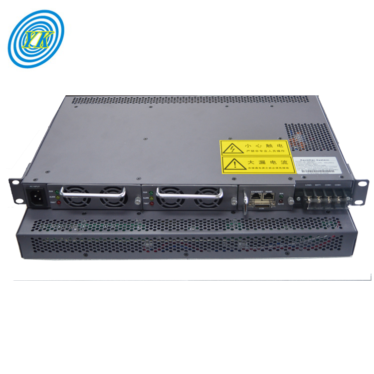
Mastering Rectifier Systems: From Diodes to Inverters and Beyond
Click: 1027 Date: 01/22/2024 3::50::18 PM
Mastering Rectifier Systems: From Diodes to Inverters and BeyondThe heart of every rectifier is the diode, a semiconductor device that plays a crucial role in converting alternating current (AC) into direct current (DC). The diode achieves this by allowing current to flow in one direction, thus ensuring that the output is always a direct current.There are different types of diodes, each with unique properties and uses. For instance, the Schottky diode, named after the German physicist Walter H. Schottky, is a type of diode that features a low forward voltage drop and a very fast switching action. This makes it particularly useful in applications where speed and efficiency are paramount.The basic function of a diode in a rectifier is to allow one-way flow of electric charge. This is the principle behind the simplest kind of rectifier circuit, known as the half-wave rectifier. This type of rectifier only allows one half of an AC waveform to pass through to the load.In conclusion, understanding the properties and functions of diodes is essential in mastering the principles of rectifiers. Whether it's the Schottky diode or a simple silicon diode, the role of the diode in rectifying AC to DC cannot be overstated.Rectifiers play a pivotal role in converting Alternating Current (AC) into Direct Current (DC), making them indispensable in numerous electronic circuits. Two common types of rectifiers are the Full Wave Rectifier and the Half Wave Rectifier. Each type has its unique characteristics and applications.A Full Wave Rectifier is designed to convert both the positive and negative cycles of an AC waveform into DC. This type of rectifier operates by passing the AC signal through a bridge of four diodes, which allow current to flow in both directions during the positive and negative cycles of the AC signal. As a result, the output DC voltage has a peak value equal to the peak value of the input AC voltage.On the other hand, a Half Wave Rectifier only converts the positive half of the AC waveform into DC. This rectifier operates by allowing current to flow in one direction through a single diode. Consequently, the output DC voltage has a peak value equal to the peak value of the input AC voltage, but the negative half of the AC waveform is eliminated. Despite its simplicity, a half-wave rectifier is widely used due to its lower cost and smaller size compared to a full-wave rectifier.While both types of rectifiers serve the purpose of converting AC to DC, the choice between a full-wave and a half-wave rectifier depends on the specific application. For instance, if the application requires the DC voltage to remain constant regardless of the polarity of the AC input, a full-wave rectifier would be the preferred choice. However, if the application does not require the DC voltage to be positive during the negative cycle of the AC input, a half-wave rectifier could suffice.In conclusion, understanding the differences between full-wave and half-wave rectifiers is essential for selecting the appropriate rectifier for a given application. While full-wave rectifiers offer smoother DC output, they are more complex and expensive. In contrast, half-wave rectifiers are simpler and cheaper, but they produce a pulsating DC output.Bridge rectifiers are vital electronic components that transform alternating current (AC) into direct current (DC), providing a stable and constant DC voltage for various devices and systems. This transformation is crucial for powering electronic gadgets and systems that necessitate a steady DC voltage.The primary function of a bridge rectifier is to convert AC voltage, which periodically alters its polarity, into a unidirectional voltage, or DC. This conversion process is known as rectification. Bridge rectifiers are composed of four diodes arranged in a specific configuration referred to as a “bridge” or a “diamond” arrangement.During the positive half cycle of the AC input, two of the diodes become forward-biased and conduct current, while the other two are reverse-biased and do not conduct. This allows the current to flow in one direction, generating a positive output voltage.In contrast, during the negative half cycle, the roles of the diodes are reversed, with the previously reverse-biased diodes becoming forward-biased and conducting current. This leads to the negative input voltage being transformed into a positive output voltage. The output waveform, after being smoothed by a smoothing capacitor, closely mirrors a continuous DC voltage.Bridge rectifiers offer full-wave rectification that is efficient and adaptable, considering voltage drop and efficiency. This full-wave rectification is achieved by the alternating action of the diodes, which separates the negative and positive halves of the AC waveform. The diodes effectively "cut off" the portions allowing only the positive portions to pass through.The output from the Bridge Rectifier is a stream of current (DC), representing a flow of electricity in a direction similar to a steady river stream.In summary, bridge rectifiers play a significant role in electronics by converting alternating current (AC) into stable direct current (DC). Understanding the construction, operational principles, benefits, and uses of rectifiers is crucial when selecting a rectifier for specific electrical requirements.The role of power supplies in rectifier systems is crucial as they act as the foundation for converting alternating current (AC) into direct current (DC). A power supply provides the necessary DC power for the application. In essence, it's the power distribution system that feeds the rectifier with the required AC power which is then converted into DC by the rectifier.In industrial settings, power supplies are often specified based on the voltage applied, current needed in the process, quality of the power, and how the control will be arranged. The ripple, which is the clarity of the power, is an important measure for determining the efficiency and quality of a rectifier.There are several types of power supplies available, each with its own advantages and disadvantages. For instance, SCR rectifiers are variable voltage DC power supplies that are low frequency, high ripple systems. These systems are rugged and have a history of durability in the market. On the other hand, switch mode power supplies (SMPS) are electronic power supplies that use a switch from AC to DC, back to AC, then once again back to DC. This is all done at high frequency allowing for the internal parts to be smaller.In conclusion, the power supply plays a vital role in rectifier systems by providing the necessary AC power that the rectifier converts into DC. The choice of power supply depends on the specific requirements of the application, including factors such as voltage, current, and power quality.Inverters and voltage regulators play crucial roles in rectifier systems, performing functions that complement each other to ensure optimal operation of the system.An inverter is a device that converts direct current (DC) back into alternating current (AC). This is particularly useful in situations where the rectified DC needs to be converted back into AC for certain applications. For instance, an inverter can be used to power AC devices from a DC source. It's worth noting that the process of converting DC to AC is essentially the reverse operation of rectification, hence the name "inverter" 5.On the other hand, a voltage regulator is a key component that helps maintain a steady and constant output voltage from the rectifier system. This is essential for many applications where a stable DC voltage is required. The regulator works by controlling the current supplied to the load to achieve a constant output voltage. It's designed to react to variations in the supply and load characteristics, ensuring the output voltage remains within the desired range 5.In summary, inverters and voltage regulators are integral parts of rectifier systems, playing vital roles in converting and stabilizing power. Understanding how they work and interact can provide valuable insights into the functioning of these complex systems.Rewrite